Machine tool assembly error prediction and control method

An assembly error and control method technology, applied in computer-aided design, special data processing applications, instruments, etc., can solve the failure to consider the transmission of guide rail errors, lack of scientific theoretical analysis and guidance specifications, and the amount of anti-deformation control is not very good Accurate and other issues, to achieve the effect of reducing repeated scraping work, accurate and efficient guidance of machine tool assembly work

Active Publication Date: 2019-08-06
TIANJIN UNIV
View PDF7 Cites 9 Cited by
  • Summary
  • Abstract
  • Description
  • Claims
  • Application Information

AI Technical Summary

Problems solved by technology

[0003] There is no clear and effective guidance method for guide rail installation and adjustment, which takes up a lot of time in the assembly process. Technicians often ignore the effect of guide rail errors on the error transfer of sliders and moving parts under the effect of geometric errors such as straightness on the rolling joint surface.
At the same time, the gravity deformation of parts during the assembly process has a great influence on the assembly error. At present, the anti-deformation strategy is often used to compensate for the assembly work of machine tools, but the control amount of anti-deformation is not very accurate, and the transfer effect of the guide rail error is not considered. Failure to establish a functional relationship between the deformation deviation and the homogenization of the guide rails and the final assembly error
[0004] Therefore, the current traditional assembly process mainly depends on the experience of workers, lacks scientific theoretical analysis and guidance specifications, and it is difficult to guarantee assembly reliability and low assembly efficiency.

Method used

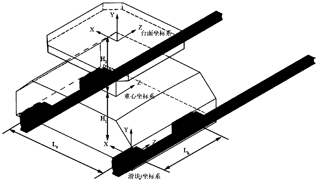
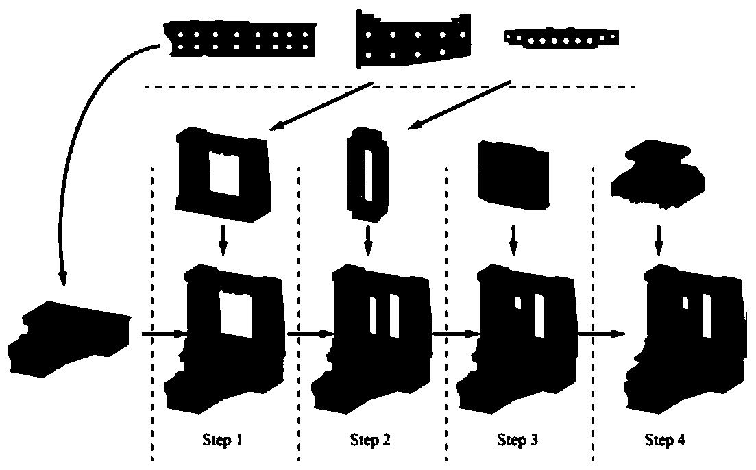
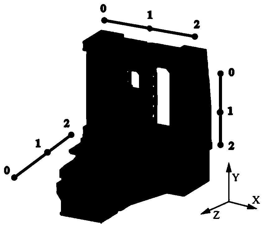

Image

  • Machine tool assembly error prediction and control method
  • Machine tool assembly error prediction and control method
  • Machine tool assembly error prediction and control method

Examples


Embodiment Construction

[0049] The present invention will be described in further detail below in conjunction with the accompanying drawings and specific embodiments. It should be understood that the specific embodiments described here are only used to explain the present invention, not to limit the present invention.

[0050] 1 Rolling guide error-worktable error transfer model establishment

[0051] 1.1 Hertz Contact Theory

[0052] According to the Hertz contact theory, the relationship between contact deformation and contact pressure is:

[0053]

[0054] In engineering applications, because the force of the roller is very complicated, its empirical formula is mainly used (reference: Zhupanska O I. Contact problem for elastic spheres: Applicability of the Hertz theory to non-small contact areas[J].International Journal of Engineering Science, 2011, 49(7):576-588.):

[0055]

[0056] Among them, E 1 ,E 2is the modulus of elasticity of the roller and the raceway surface; υ 1 , υ 2 Is t...


PUM


Abstract

The invention discloses a machine tool assembly error prediction and control method which comprises the following steps: (1) based on a Hertz contact theory, establishing and linearing a rolling guiderail error-workbench error transfer model based on deformation coordination; (2) for a precise horizontal machining center, establishing a finite element model by means of ABAQUS simulation software,and extracting a gravity deformation result of each assembly step; (3) on the basis of an assembly error transfer model based on a differential vector method, establishing a complete machine error model considering assembly deformation and guide rail errors; and (4) for the established complete machine error model, providing a corresponding assembly error adjustment and control strategy. The influence of the rolling guide rail geometric error on error transmission is comprehensively considered, and the method better conforms to the objective installation condition; the variability of gravitydeformation is considered, the deformation result is analyzed step by step, and step-by-step prediction and tail end error control are achieved more accurately.

Description

technical field [0001] The invention relates to the field of assembling and testing of numerically controlled machine tools, in particular to a method for predicting and controlling machine tool assembling errors taking into account rolling guide rail errors and gravity deformation of structural parts. Background technique [0002] High-speed, high-precision, and high-reliability precision machining centers have become the development direction of modern equipment manufacturing [1]. Many countries regard the development of precision CNC machine tools as the primary task of developing high-end manufacturing. As an important CNC machine tool, the precision horizontal machining center has a series of advantages such as high degree of automation and high processing efficiency, and is widely used in aerospace, aviation, precision mold processing and other fields. [0003] There is no clear and effective guidance method for guide rail installation and adjustment, which takes up a ...

Claims


Application Information

Patent Timeline
Patent Type & Authority Applications(China)
IPC IPC(8): G06F17/50
CPCG06F2119/06G06F30/20Y02P90/02
Inventor 何改云史盼盼郭龙真孙光明张大为
Owner TIANJIN UNIV
Why Eureka
Try Eureka