Power grid line fault isolation device and method

A line fault and isolation device technology, applied in emergency protection circuit devices, electrical components and other directions to ensure stable operation

Pending Publication Date: 2019-08-06
YANGZHOU POLYTECHNIC COLLEGE
View PDF1 Cites 2 Cited by
  • Summary
  • Abstract
  • Description
  • Claims
  • Application Information

AI Technical Summary

Problems solved by technology

Since there is no unified model for the domestic distribution network automation system at present, the implementation methods of feeder automation for distribution network automation systems composed of different equipment and different design schemes are different.

Method used


Image

  • Power grid line fault isolation device and method
  • Power grid line fault isolation device and method
  • Power grid line fault isolation device and method

Examples


Embodiment 1

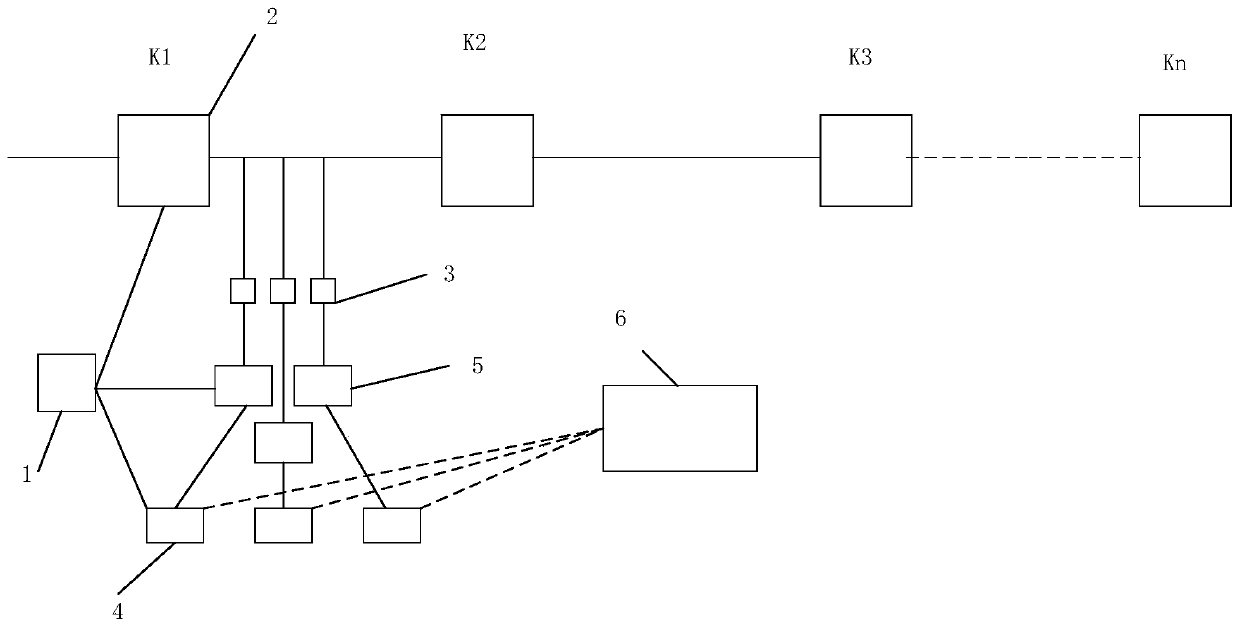
[0035] A power grid line fault isolation device, including: a distribution network and users at the end of the distribution network, and also includes: a processor 1, a section switch 2, a circuit breaker 3, a wireless communication module 4, a ground fault judging device 5 and a substation server 6;

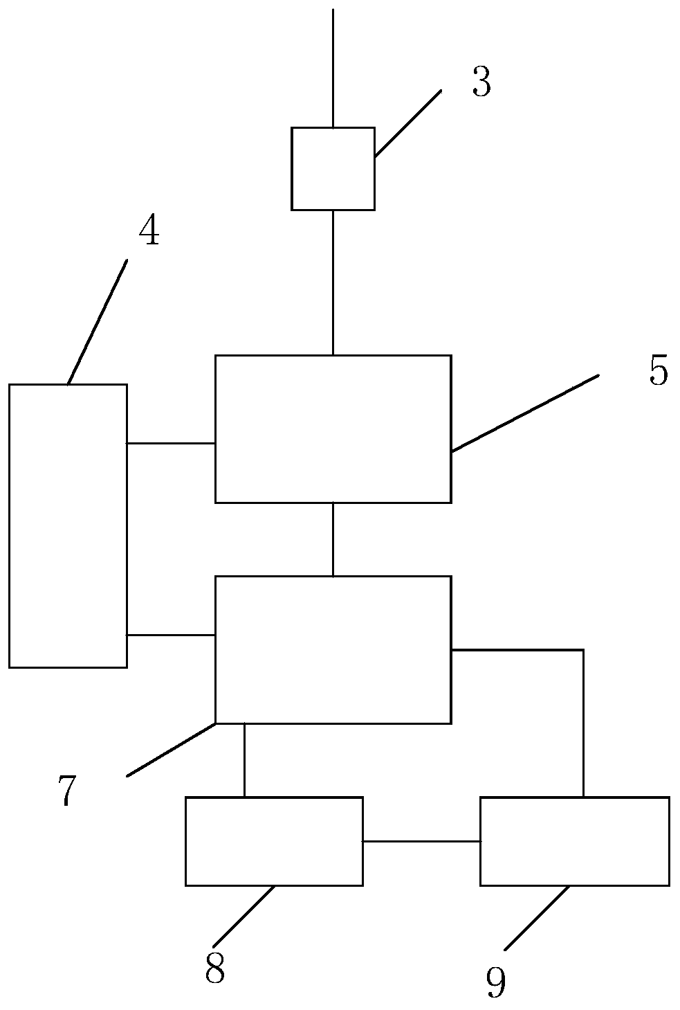
[0036] Wherein, the section switch 2 is arranged on the trunk road of the distribution network; the circuit breaker 3 is installed on the branch road of the distribution network; the circuit breaker 3 is connected with the ground fault judging device 5; the processor 1 is respectively connected with the wireless communication module 4, the ground fault The judging device 5 and the section switch 2 are electrically connected; the processor 1 and the substation server 6 perform information exchange through the wireless communication module 4 .

[0037] In order to further optimize the above technical scheme, the ground fault judging device 5 includes: a zero-sequence voltage trans...

Embodiment 2

[0044] A power grid line fault isolation method, the specific steps include:

[0045] Step 1: Number the section switch 2 as K1, K2, ..., Kn; number the user branch circuit breaker 3 as K 用户11 , K 用户12 ,...,K 用户21 , K 用户22 ,...,K 用户nn ;

[0046] Step 2: The ground fault judging device 5 transmits the collected voltage and current signals on the branch lines to the processor 1;

[0047] Step 3: The processor 1 compares the voltage and current signals with the preset threshold; if abnormal, the processor 1 controls the circuit breaker 3 to disconnect;

[0048] Step 4: If the substation server 6 cannot receive the signal of the wireless communication module 4 of the continuous user, then the main road fails; the substation server 6 and the corresponding processor 1 send instructions to control the section switch 2 to disconnect;

[0049] Step 5: Realize the fault isolation of the trunk road.

[0050] In order to further optimize the above technical solution, in step 2, the...

Embodiment 3

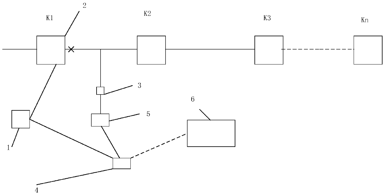
[0052] Such as image 3 As shown, each wireless communication module of the branch after the sub-section switch K1 cannot interact with the server wireless communication module, indicating that the main road is faulty, and the possibility of a fault in the K1-K2 section is high, and the maintenance personnel will carry out emergency repairs for this section. When the fault prediction device is used for recovery, when a fault occurs, the dispatcher controls the fault prediction device through the substation server. After receiving the pre-judgment instruction, the high-voltage generator uses the shaker test principle to perform high-voltage charging prediction on the faulty line , if it is predicted that power can be transmitted, then close the power transmission switch to transmit power.


PUM


Abstract

The invention discloses a power grid line fault isolation device. The device comprises a power distribution network and terminal users of the power distribution network, and is characterized by also comprising a processor, a section switch, a circuit breaker, wireless communication modules, a grounding fault determining device and a transformer station server; the section switch is arranged in a trunk of the power distribution network; the circuit breaker is installed in a branch of the power distribution network, and connected with the grounding fault determining device; the processor is electrically connected with the wireless communication modules, the grounding fault determining device and the section switch; and the processor makes information interaction with the transformer stationserver via the wireless communication module. The invention also provides a power grid line fault isolation method. Via the device and method, a fault section can be located rapidly, and a fault can be isolated; the power failure scope can be minimized, power failure time in a non-fault section is short, and power utilization is more reliable; and power is delivered timely when a power delivery condition is met, and the power delivery efficiency is improved.

Description

technical field [0001] The invention relates to the technical field of power system automation, and more specifically relates to a power grid line fault isolation device and method. Background technique [0002] In the distribution network, the neutral points of 10kV and 35kV systems are generally operated in an ungrounded manner. Among them, the single-phase ground fault accounts for more than 70% of the total faults, and nearly 93% of the ground fault points occur in the overhead line after the accident line investigation analysis. At present, power companies only use trial stops to find the faulty line for such faults. Therefore, after the single-phase grounding accident occurs, in order to find the faulty line, it is inevitable to repeatedly cut off the power to the normal power supply users, which greatly reduces the reliability of power supply to users. sex. It is stipulated in the power dispatching regulations that when a ground fault occurs in the 10kV and 35kV sys...

Claims


Application Information

Patent Timeline
Patent Type & Authority Applications(China)
IPC IPC(8): H02H7/28
CPCH02H7/28
Inventor 张建宏张兆东张翔周益军周军高艳朱亚东
Owner YANGZHOU POLYTECHNIC COLLEGE
Why Eureka
Try Eureka