
Isolation circuit

A technology of isolating circuits and isolating capacitors, which is applied in the direction of logic circuit interface devices, logic circuit connection/interface layout, etc., can solve the problems of no competitive advantage in cost, complex circuits, and reduced light intensity

Pending Publication Date: 2019-08-06
深圳市红芯微科技开发有限公司
View PDF0 Cites 5 Cited by
  • Summary
  • Abstract
  • Description
  • Claims
  • Application Information

AI Technical Summary

Problems solved by technology

A typical isolation solution for this type of application is an optocoupler, which has a thick internal insulation to withstand high voltages, but has the disadvantage of using light-emitting diodes (LEDs), whose light intensity decreases over time and with temperature. design and reliability issues
Because of its stable quality, long life, and more and more applications, capacitive isolation has a tendency to replace optical isolation. At present, the isolation scheme using carrier technology needs to transmit and receive high-frequency carrier waves, so the power consumption is high, the circuit is complicated, and the cost is lower than that of optical isolation. coupling isolation has no competitive advantage

Method used


Image

  • Isolation circuit
  • Isolation circuit
  • Isolation circuit

Examples


Embodiment Construction

[0031] In order to make the purpose, technical solutions and advantages of the embodiments of the present invention more clear, the following will clearly and completely describe the technical solutions of the embodiments of the present invention in conjunction with the drawings of the embodiments of the present invention. Apparently, the described embodiments are some, not all, embodiments of the present invention. Based on the described embodiments of the present invention, all other embodiments obtained by persons of ordinary skill in the art without creative effort fall within the protection scope of the present invention.

[0032] Unless otherwise defined, the technical terms or scientific terms used herein shall have the usual meanings understood by those skilled in the art to which the present invention belongs. "First", "second" and similar words used in the patent application specification and claims of the present invention do not indicate any order, quantity or impo...


PUM


Abstract

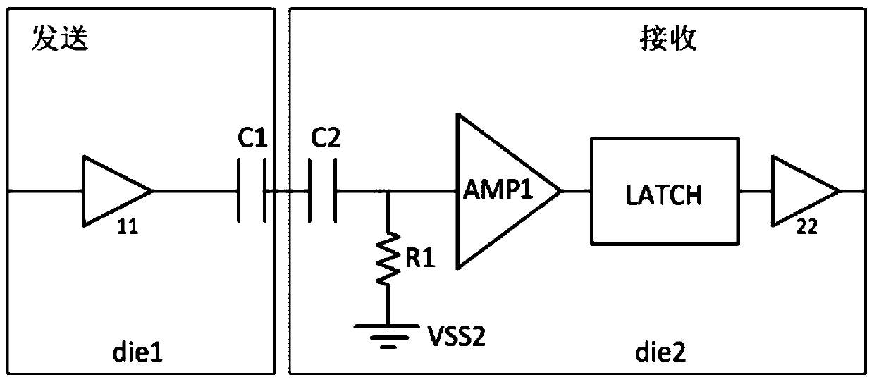
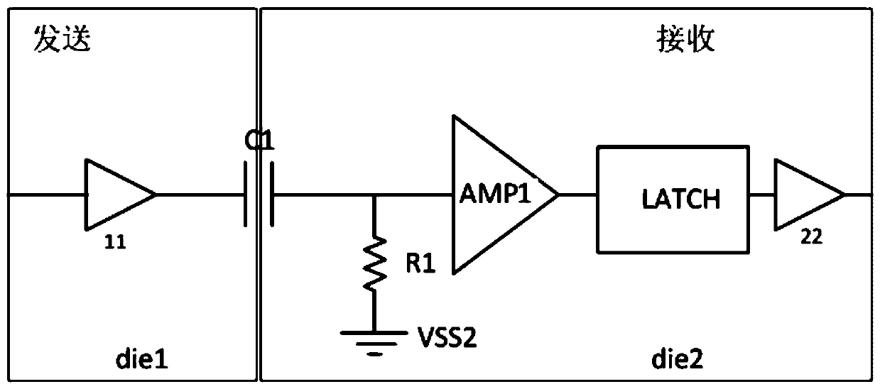
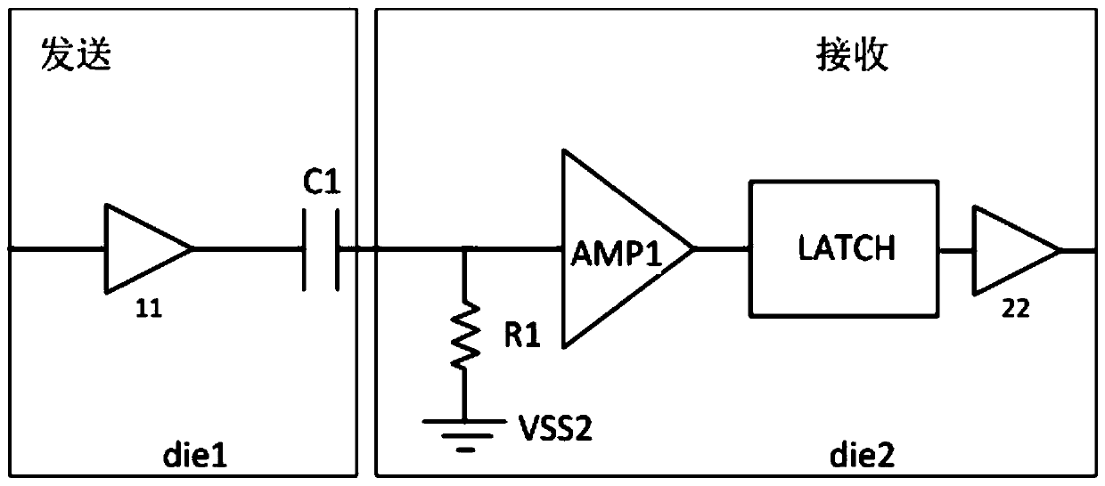
The invention relates to an isolation circuit. The isolation circuit comprises an isolation capacitor module, a first sampling resistor, a first amplifier and a latch; the first sampling resistor, thefirst amplifier and the latch are positioned on the second tube core; one end of the isolation capacitor module receives an input signal; the other end of the isolation capacitor module is connectedwith one end of a first sampling resistor and the input end of a first amplifier; the output end of the first amplifier is connected with the input end of the latch, the other end of the first sampling resistor is grounded, the isolation capacitor module comprises one or more isolation capacitors, the isolation capacitor module is located on the first tube core and / or the second tube core, and thegrounding end of the first tube core and the grounding end of the second tube core are not grounded in common. High isolation voltage can be achieved through the isolation circuit, and a CMOS technology is adopted in the whole technical scheme.

Description

technical field [0001] The invention relates to an isolation circuit. Background technique [0002] In harsh application environments, applications require protection against high-voltage transients, protection against data corruption, and the elimination of the effects of high-voltage electrical stress on the isolation life of the isolator. A typical isolation solution for this type of application is an optocoupler, which has a thick internal insulation to withstand high voltages, but has the disadvantage of using light-emitting diodes (LEDs), whose light intensity decreases over time and with temperature. This creates design and reliability issues. Because of its stable quality, long life, and more and more applications, capacitive isolation has a tendency to replace optical isolation. At present, the isolation scheme using carrier technology needs to transmit and receive high-frequency carrier waves, so the power consumption is high, the circuit is complicated, and the c...

Claims


Application Information

Patent Timeline
IPC IPC(8): H03K19/0175
CPCH03K19/017509
Inventor 徐群
Owner 深圳市红芯微科技开发有限公司
Learn More