A self-centering two-way rotating cross-axis machining spindle

A bidirectional rotation and processing spindle technology, which is applied in metal processing equipment, metal processing machinery parts, positioning devices, etc., can solve the problems that do not conform to the concept of high-efficiency development, coaxial precision cannot be guaranteed, and the purchase price of machine tools is high. Easy to move and install, compact structure, and low manufacturing cost

Inactive Publication Date: 2020-06-30
福清薛记数控科技有限公司
View PDF10 Cites 0 Cited by
  • Summary
  • Abstract
  • Description
  • Claims
  • Application Information

AI Technical Summary

Problems solved by technology

[0004] 1. Only one of the end holes 102 can be processed at a time, and four times of clamping are required to process a cross-axis workpiece 10, which is cumbersome and inefficient;
[0005] 2. Due to the defects described in 1., the coaxial accuracy of the two aligned end holes 102 in the cross-axis workpiece 10 cannot be guaranteed
[0006] 3. Rely on machine tool equipment for processing. When mass production and processing, at least one machine tool equipment must be specially equipped for processing. The purchase price of machine tool equipment is generally high, which does not conform to the concept of high-efficiency development of modern enterprises

Method used


Image

  • A self-centering two-way rotating cross-axis machining spindle
  • A self-centering two-way rotating cross-axis machining spindle
  • A self-centering two-way rotating cross-axis machining spindle

Examples


Embodiment 1

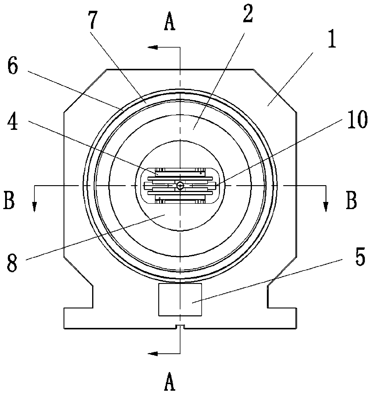
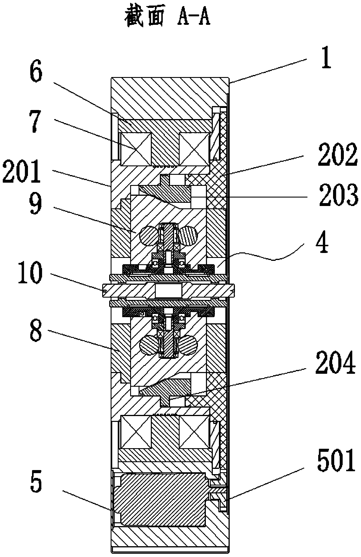
[0059] The present invention is a kind of self-centering two-way rotating cross-axis machining spindle, such as Figure 16 As shown, the device b is installed on the platform a, and the processing spindle c is symmetrically installed on both sides of the device b. The processing spindle c can rotate by itself and move forward and backward along the axial direction. When clamping, the cross-axis workpiece 10 is loaded and unloaded from the workpiece The port 802 is placed between the two groups of reversing clamping discs 406, and the four shafts 101 are respectively dropped into the V-shaped limit blocks on the clamping flange 408, and then the rotary cylinder mechanism 2 is driven to make the rotary cylinder mechanism 2. The piston ring 203 of the middle oil cylinder moves to the left to abut against the lifting installation block 9, and pushes the lifting installation block 9 to move to the middle, that is, to move the clamping reversing mechanism 4 to the middle, and the two...

Embodiment 2

[0061] Different from Embodiment 1, the two groups of processing spindles c in this embodiment do not have the power of rotation, but can only move forward and backward in opposite directions. Under this condition, when processing the cross-axis workpiece 10, the reduction motor 5 needs to be turned on, and the drive gear 501 and the rotary oil cylinder The meshing of the end of the outer wall of the mechanism 2 drives the rotation of the rotary cylinder mechanism 2, that is, drives the clamped cross-axis workpiece 10 to rotate, and can also realize the processing of the end hole 102. At this time, the strength is suitable for use with unpowered external processing tools.


PUM


Abstract

The invention discloses a self-centering bidirectional rotating cross shaft machining main shaft in the technical field of precision machining equipment. The self-centering bidirectional rotating cross shaft machining main shaft comprises a device shell, a rotating oil cylinder mechanism, a lifting mechanism, clamping reversing mechanisms, positioning mechanisms and a speed reducing motor, whereina bearing fixing sleeve and a pair of angular contact bearings are fixedly attached to an inner cavity of the device shell; the lifting mechanism is arranged in an inner cavity of the rotating oil cylinder mechanism; the lifting mechanism comprises a lifting frame body and two lifting installation blocks; the clamping reversing mechanisms is provided with two groups symmetrical at up and down; the two groups of clamping reversing mechanisms clamp and fix a cross shaft workpiece by mutually approaching; the positioning mechanism is provided with two groups which symmetrical at back and forth and are respectively embedded on the front side and the back side of the lifting frame body and used for positioning two opposite shaft ends in the cross shaft workpiece; and the speed reducing motor is embedded below the device shell and used for driving the rotating oil cylinder mechanism to rotate. The self-centering bidirectional rotating cross shaft machining main shaft is used for machining the cross shaft workpiece.

Description

technical field [0001] The invention relates to the technical field of precision machining equipment, in particular to a self-centering bidirectional rotating cross axis machining spindle. Background technique [0002] With the development of modern science and technology, the level of mechanical processing and manufacturing technology has improved. Machining accuracy determines product quality and has become one of the standards for measuring an industrial level. Machining accuracy is the relationship between the actual size, shape and position of the surface of the processed part. The degree of compliance with the ideal geometric parameters required by the drawings. The ideal geometric parameters, in terms of size, are the average size; in terms of surface geometry, they are absolute circles, cylinders, planes, cones and straight lines, etc.; in terms of mutual positions between surfaces, they are absolute parallelism , vertical, coaxial, symmetrical, etc. The deviation ...

Claims


Application Information

Patent Timeline
Patent Type & Authority Patents(China)
IPC IPC(8): B23B19/02B23Q3/12
CPCB23Q1/70B23Q3/12
Inventor 曾斌鸿
Owner 福清薛记数控科技有限公司
Why Eureka
Try Eureka