
3D-printing concrete molding equipment capable of realizing aggregate piling and slurry flowing and molding method

A technology of 3D printing and molding equipment, applied in the field of 3D printing, can solve the problems of 3D printing construction quality, high cement consumption, large volume shrinkage, etc., and achieve the effects of novel design, low production cost, and simple molding process

Pending Publication Date: 2019-08-09
CHINA STATE CONSTRUCTION ENGINEERING CORPORATION
View PDF0 Cites 3 Cited by
  • Summary
  • Abstract
  • Description
  • Claims
  • Application Information

AI Technical Summary

Problems solved by technology

[0009] However, the printed concrete used in the current concrete 3D printing technology is a mortar material, there is no 2-25mm coarse aggregate, and no steel fiber is added to solve the brittleness of plain concrete; in addition, the mortar material has a high amount of cement and a large volume shrinkage during hydration , easy to crack, causing quality problems of 3D printed buildings

Method used


Image

  • 3D-printing concrete molding equipment capable of realizing aggregate piling and slurry flowing and molding method
  • 3D-printing concrete molding equipment capable of realizing aggregate piling and slurry flowing and molding method
  • 3D-printing concrete molding equipment capable of realizing aggregate piling and slurry flowing and molding method

Examples


Embodiment 1

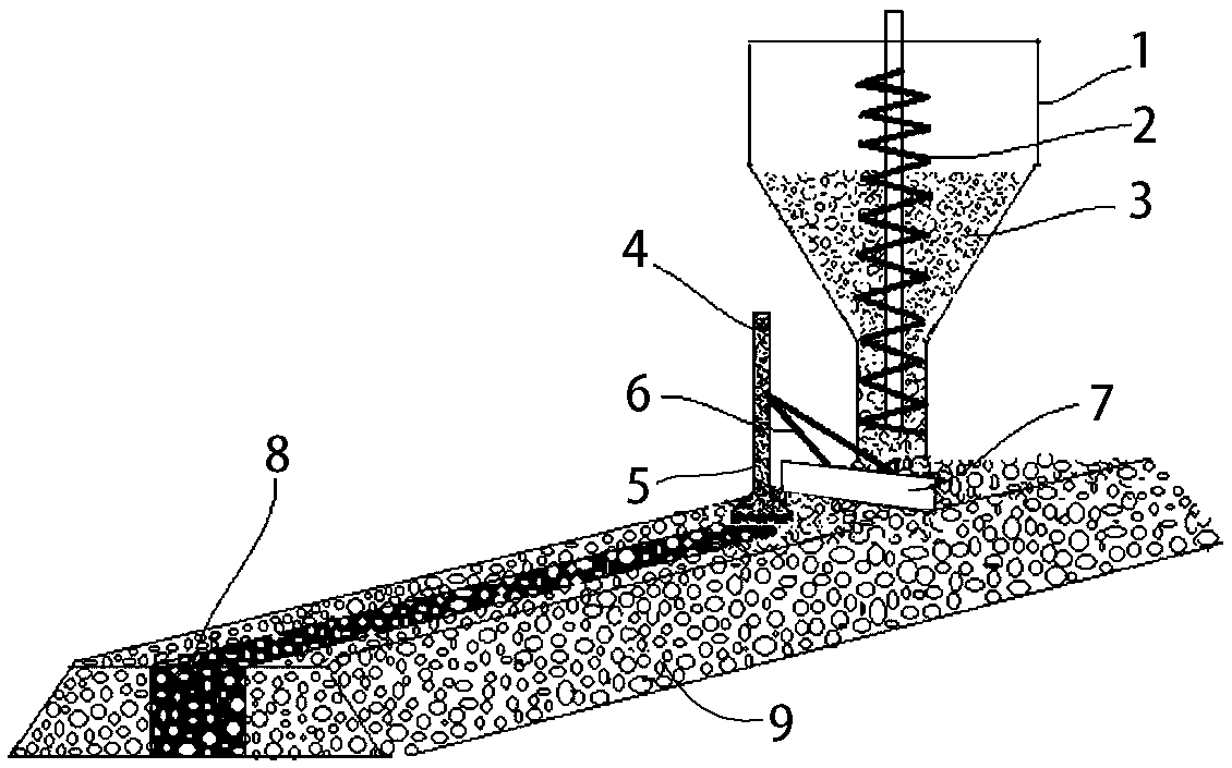
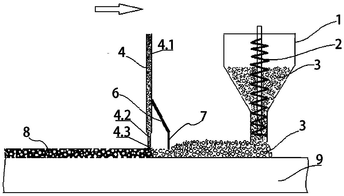
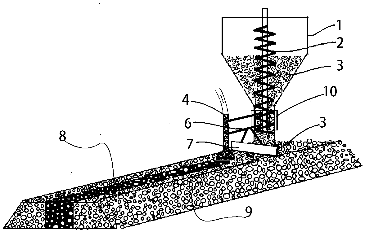
[0045] The principles and features of the present invention are described below in conjunction with the accompanying drawings, and the examples given are only used to explain the present invention, and are not intended to limit the scope of the present invention. Such as figure 1 and figure 2It is the first embodiment of the present invention, a 3D printing concrete forming equipment for stacking aggregate flow slurry, including a feeding system, a moving mechanism, a printing head and a control system, and the printing head includes a printing hopper 1 and a printing nozzle arranged vertically in parallel 4. The printing hopper 1 is equipped with a conveying screw blade 2; the printing nozzle 4 is equipped with a nozzle flow control valve. The nozzle flow control valve is not shown in the attached drawing and is directly controlled by the back-end slurry conveyor. The feeding of the printing hopper 1 The feeding port is connected with the feeding system of the aggregate 3, ...


PUM

PropertyMeasurementUnit
Particle sizeaaaaaaaaaa

Abstract

The invention provides 3D-printing concrete molding equipment capable of realizing aggregate piling and slurry flowing and a molding method. A printing head of the equipment comprises a printing hopper and a printing nozzle which are arranged in parallel, wherein the feeding port of the printing hopper communicates with an aggregate feeding system, and the feeding port of the printing nozzle communicates with a feeding system of fast-setting thixotropic cement slurry; the printing hopper and the printing nozzle are arranged front and back and move forwards in the same route; a scraping plate is arranged in the middle and used for scraping aggregate. During printing, aggregate is distributed first, then fast-setting thixotropic cement slurry is quickly dispersed along the printing path at aconstant speed, the cement slurry flows into gaps of the aggregate and quickly sets and hardens to form a whole concrete body, the steps are repeated and a product is formed after piling layer by layer. The equipment requires a simple molding process, is high in production efficiency and low in production cost and can be applied to printing of curved walls, artistic models and decorations, the defects of no large-particle aggregate, high consumption of concrete, high shrinkage and unavailability of addition of steel fibers in current mortar 3D printing techniques are overcome, and the moldingmethod is a special 3D-printing concrete molding process.

Description

technical field [0001] The invention relates to the technical field of 3D printing, in particular to a 3D printing concrete forming equipment and a forming method of aggregate flow slurry. Background technique [0002] At present, 3D printing technology is being promoted rapidly in the field of construction. Concrete, as the most widely used construction material in construction, is the main material of construction 3D printing technology. [0003] Architectural 3D printing technology conforms to the development of the industrial revolution and has the following advantages compared with traditional construction techniques: [0004] (1) Reduce on-site construction time and improve construction efficiency through a constant construction rate; [0005] (2) There is no need to use formwork, which can reduce the waste of formwork and reduce construction costs, and improve the sustainable construction of buildings; [0006] (3) No template is used to make the building highly cus...

Claims


Application Information

Patent Timeline
IPC IPC(8): B28B1/00B33Y10/00
CPCB28B1/001B33Y10/00
Inventor 蔺喜强张涛霍亮李国友张楠戢文占
Owner CHINA STATE CONSTRUCTION ENGINEERING CORPORATION
Learn More