

Steel reinforcement cage production equipment
A technology of production equipment and steel cages, which is applied in the field of prefabricated floor slab manufacturing equipment, can solve the problems of high manufacturing cost, low work efficiency, and increased work burden of staff, and achieve the goals of reducing labor intensity, improving manufacturing efficiency, and improving construction efficiency Effect
- Summary
- Abstract
- Description
- Claims
- Application Information
AI Technical Summary
Problems solved by technology
Method used
Image

Examples
Embodiment Construction
[0044] The present invention will be further described in detail below in conjunction with the embodiments and the accompanying drawings, but the embodiments of the present invention are not limited thereto.
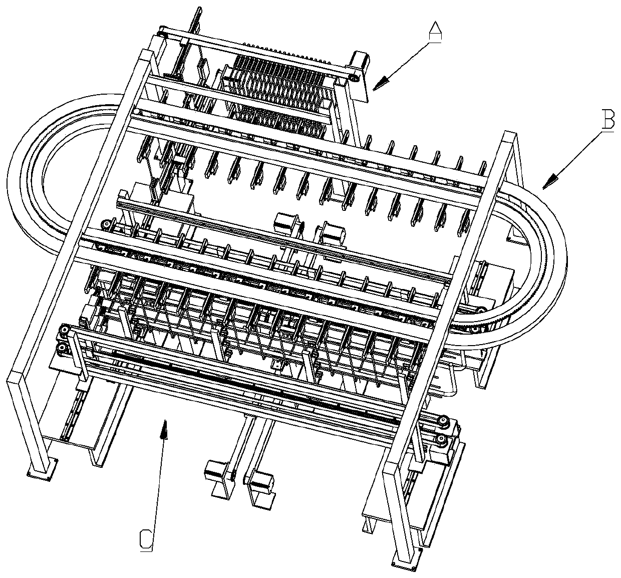
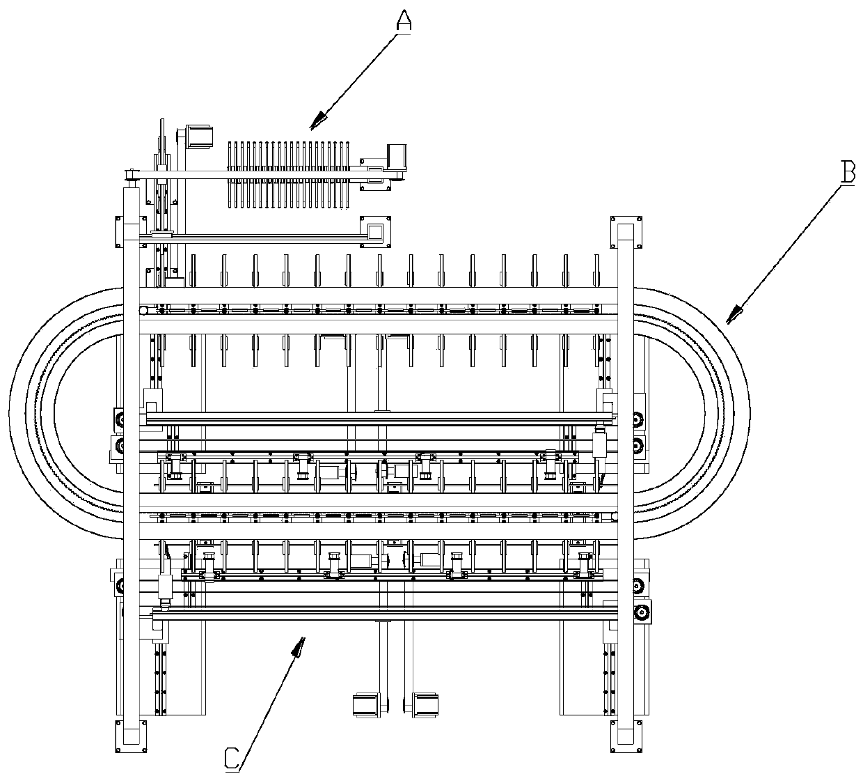
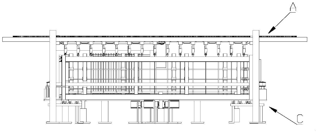
[0045] see Figure 1-Figure 26 , the steel cage production equipment of the present invention comprises stirrup automatic feeding device A, stirrup automatic conveying device B and supporting device C, wherein,
[0046] The stirrup automatic feeding device A includes a stirrup storage rack 1 for storing stirrups, a stirrup delivery seat 5, and a third stirrup delivery seat 5 for transferring the stirrups in the stirrup storage rack 1 to the stirrup delivery seat 5. A transport mechanism 2 and a second transport mechanism 3 for driving the stirrup delivery seat 5 to move towards the stirrup automatic transport device; the first transport mechanism 2 includes a first support frame 2-3, which is arranged on the first support frame 2 - the stirrup transporter 4 on 3 and the...
PUM
 Abstract
Description
Claims
Application Information