
Velocity ambiguity resolving method based on coherent frequency agile radar

A technology of frequency agility and defuzzification, which is applied in the direction of radio wave measurement systems and instruments, can solve the problems affecting the calculation efficiency of radar signal processing and target detection results, radar distance-velocity ambiguity, large calculation amount, etc., to improve calculation Efficiency and target detection accuracy, improve anti-interference ability, improve the effect of detection ability

Active Publication Date: 2019-08-09
XIDIAN UNIV
View PDF10 Cites 28 Cited by
  • Summary
  • Abstract
  • Description
  • Claims
  • Application Information

AI Technical Summary

Problems solved by technology

The disadvantage of this method is that the pulse pressure judgment threshold needs to be calculated after pulse compression. On the one hand, it increases the computational complexity; on the other hand, if the threshold calculation is inaccurate, it will affect the target detection result.
The disadvantage of this method is that in the process of looking up the table, it is necessary to make a difference between the input target velocity channel signal and the target velocity in the two-dimensional velocity defuzzification table row by column, which results in a large amount of calculation, slow table lookup speed and low efficiency.
[0005] It can be seen from the prior art that the current methods to solve the radar range-velocity ambiguity problem have problems such as large amount of calculation and inaccurate target detection results, which will affect the calculation efficiency of radar signal processing and target detection results.

Method used


Image

  • Velocity ambiguity resolving method based on coherent frequency agile radar
  • Velocity ambiguity resolving method based on coherent frequency agile radar
  • Velocity ambiguity resolving method based on coherent frequency agile radar

Examples


Embodiment 1

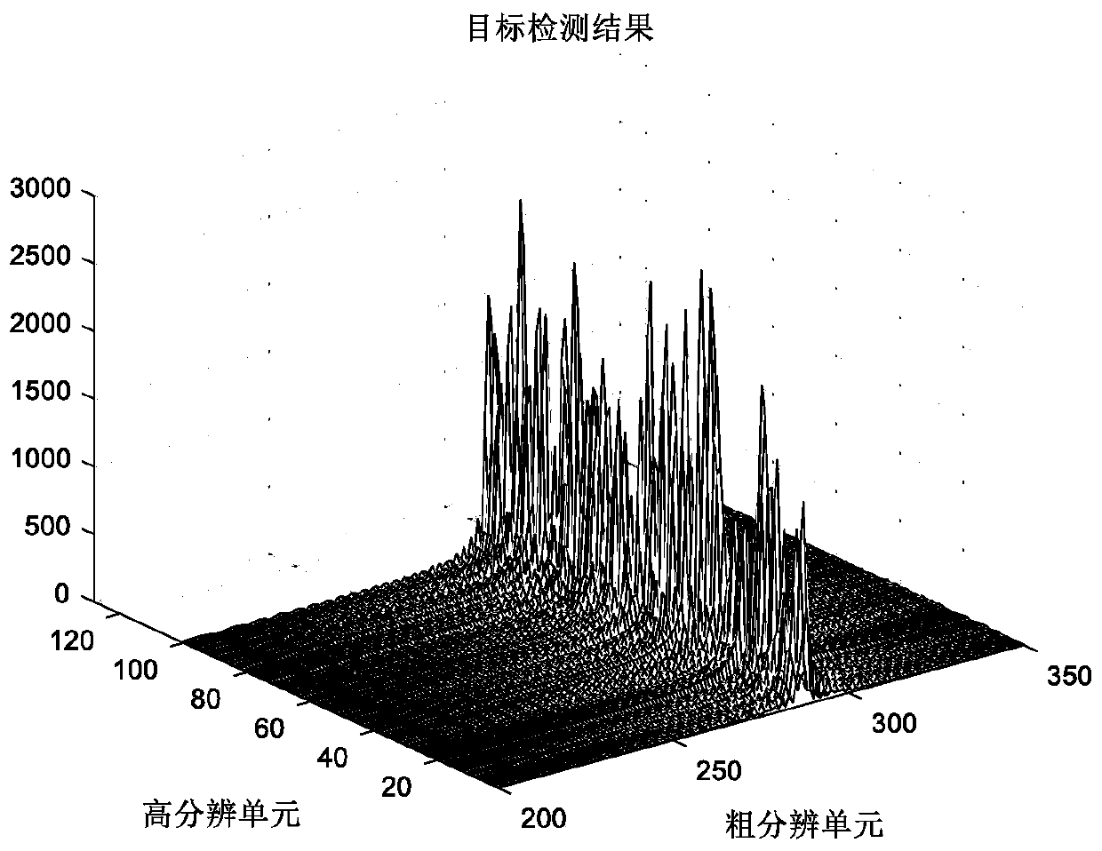
[0033] The pulse radar system is widely used because it can effectively avoid the problem of the transmitter interfering with the receiver, but the range-velocity ambiguity problem is often unavoidable in the pulse radar system. In the existing technology for solving the distance-velocity ambiguity problem, there are problems such as large amount of calculation and inaccurate target detection results. These problems will affect the calculation efficiency and target detection results. See image 3 .

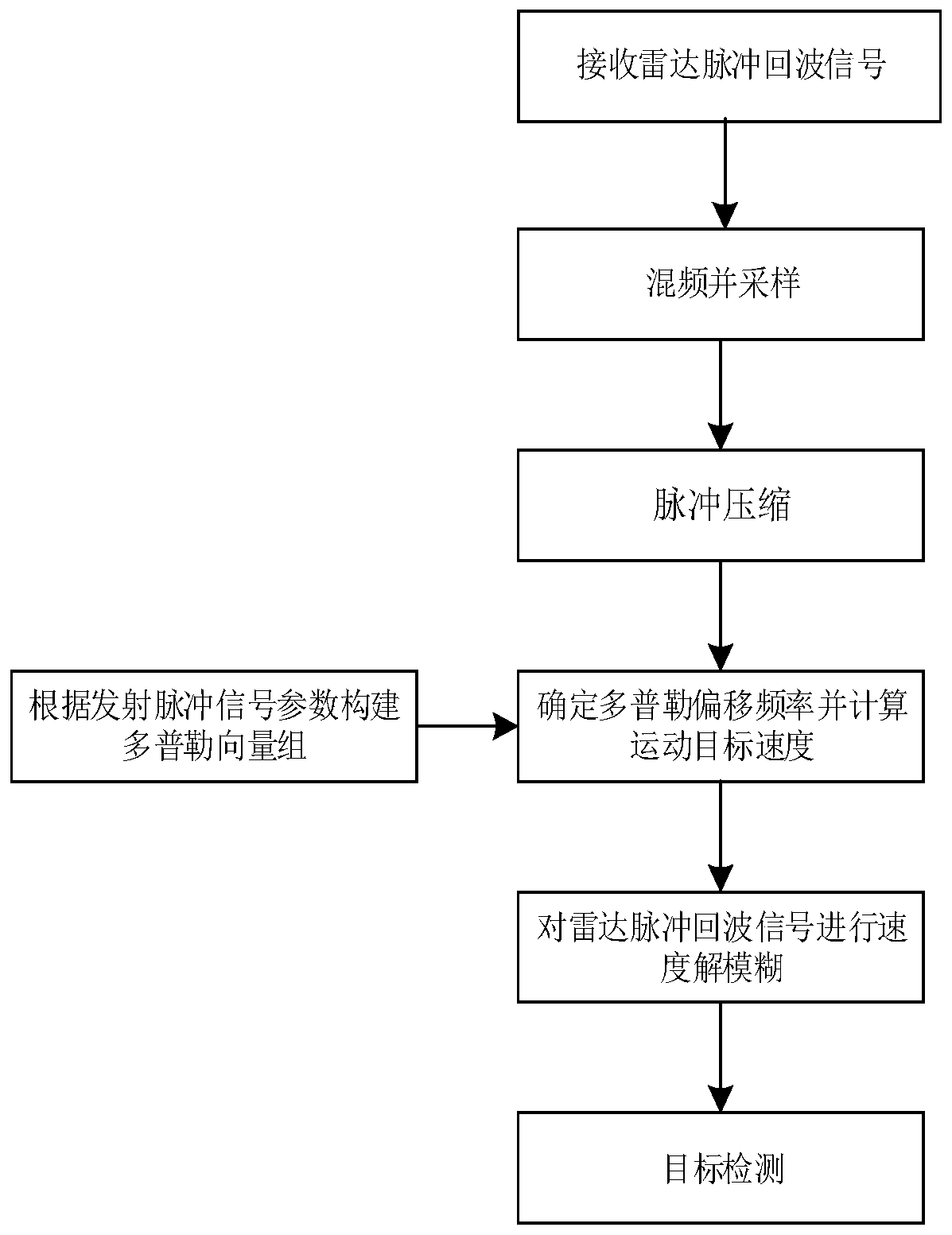
[0034] The present invention conducts research and innovation on this, and proposes a speed defuzzification method based on coherent frequency agile radar, see figure 1 , the present invention carries out velocity defuzzification to radar pulse echo signal by velocity phase compensation, carries out target detection to the radar pulse echo signal after velocity phase compensation by sparse recovery, and the present invention comprises the following steps:

[0035] (1) Receiving t...

Embodiment 2

[0053] The velocity deambiguation method based on coherent frequency agile radar is the same as embodiment 1, and the construction radar Doppler vector set described in step (4) includes the following steps:

[0054] (4a) Calculate the maximum Doppler frequency f that the radar can detect dmax , Radar minimum resolvable Doppler frequency Δf d :

[0055]

[0056] Among them, f dmax Indicates the maximum Doppler frequency that the radar can detect, then [-f dmax ,f dmax ] represents the Doppler frequency range that the radar can detect, Δf d Indicates the minimum resolvable Doppler frequency of the radar, f min Indicates the minimum value of the carrier frequency in the transmitted pulse signal, B indicates the bandwidth of the transmitted pulse signal, T r Indicates the repetition period of the radar transmitting pulse signal, B f Indicates the total frequency agility bandwidth of the radar transmitter.

[0057] (4b) Divide the Doppler frequency range detectable by t...

Embodiment 3

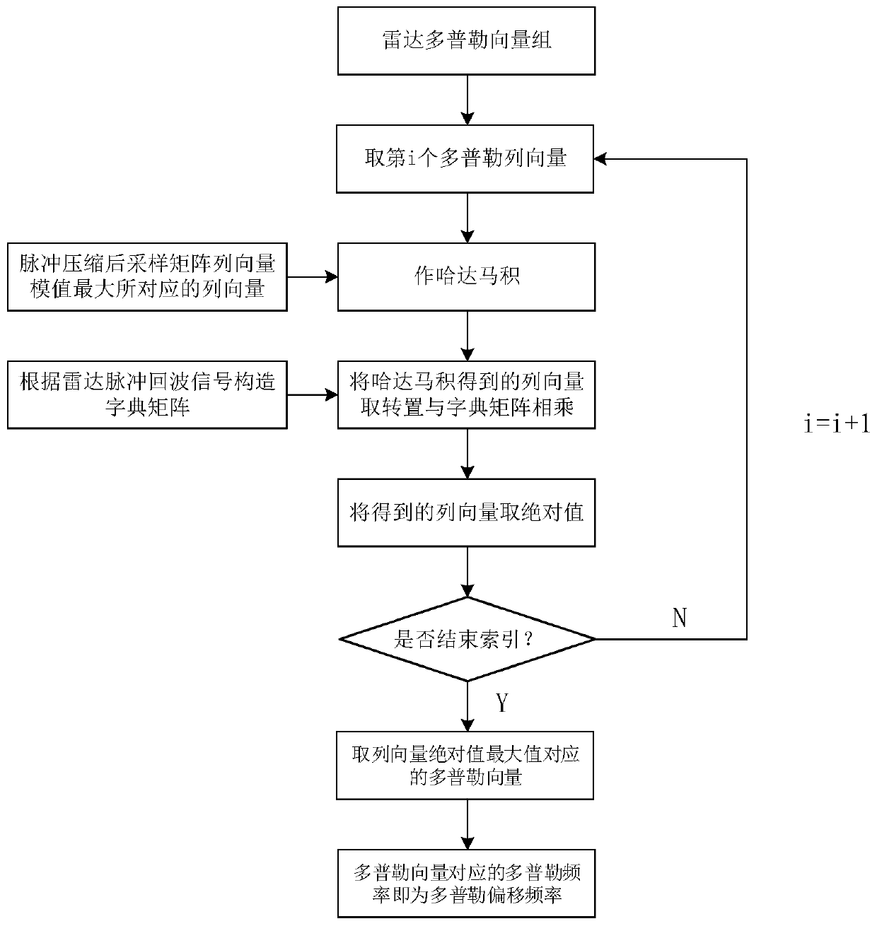
[0063] The speed defuzzification method based on the coherent frequency agile radar is the same as that of embodiment 1-2, and the flow chart of the maximum correlation method described in step (5a) can be found in figure 2 , the specific steps are:

[0064] (5a1) Construct a dictionary matrix D according to the pulse echo signal:

[0065]

[0066] Among them, D represents the dictionary matrix constructed according to the pulse echo signal, e represents the exponential operation with a natural constant as the base, j represents the arithmetic square root of -1, π represents the pi, f 1 ,f 2 ,..., f N Respectively represent different carrier frequencies in the transmitted pulse signal, and N represents the number of transmitted pulse signals. The dictionary matrix constructed by the invention is constructed according to the pulse echo signal, and the constructed dictionary matrix can be changed according to the change of the carrier frequency of the pulse echo signal. ...


PUM


Abstract

The invention discloses a velocity ambiguity resolving method based on a coherent frequency agile radar. Through the method, the problem that target detection is not accurate due to distance-velocityambiguity in pulse radar system signal processing is solved. According to the implementation method, a radar pulse echo signal is received; a baseband pulse echo signal sampling matrix is obtained; pulse compression is performed; a radar Doppler vector group is constructed; Doppler offset frequency is determined, and the velocity of a motion target is calculated; velocity ambiguity resolving is performed on the radar pulse echo signal; and target detection is performed through sparse recovery. According to the method, the accurate velocity of the motion target is calculated through the Dopplervector group, velocity phase compensation is performed on the radar pulse echo signal to realize velocity ambiguity resolving, and the target is detected through sparse recovery. The method is low ininterception and resistant to interference, the velocity of the motion target can be accurately calculated, complexity is low, and the problem of distance-velocity ambiguity in pulse radar system signal processing can be solved. The method is applied to the field of radar target detection.

Description

technical field [0001] The invention belongs to the technical field of radar signal processing, relates to the range-velocity ambiguity problem existing in the pulse radar system, and specifically relates to a velocity defuzzification method based on coherent frequency agile radar, which can be applied to target detection. Background technique [0002] Since the carrier frequency change of traditional LFM radar and step frequency radar is linear, the phase change law of radar echo caused by carrier frequency change and the phase change law caused by target movement are both linear, so the distance and speed are mutually coupled , there is a range-velocity ambiguity problem, see image 3 , which greatly reduces the detection ability of the target. Therefore, it is an important development direction in radar signal processing to solve the range-velocity ambiguity problem of the pulse radar system to improve the detection ability of the target. [0003] Xi'an Space Radio Techn...

Claims


Application Information

Patent Timeline
Patent Type & Authority Applications(China)
IPC IPC(8): G01S7/41G01S7/36
CPCG01S7/415G01S7/36
Inventor 全英汇董淑仙陈侠达李亚超邢孟道高霞张瑞林露吴彬彬余兆明赵佳琪赵金珊姚洪斌
Owner XIDIAN UNIV
Learn More