

Numerically controlled automatic microwave imaging lens
A technology of microwave imaging and imaging lens, which is applied in the direction of program control, computer control, general control system, etc., can solve the problems of inflexible imaging position and range, microwave imaging system cannot change focal length, and cannot meet imaging requirements, etc. The effect of imaging errors
- Summary
- Abstract
- Description
- Claims
- Application Information
AI Technical Summary
Problems solved by technology
Method used
Image


Examples
Embodiment Construction
[0046] In order to make the object, technical solution and advantages of the present invention clearer, the present invention will be further described in detail below in conjunction with the accompanying drawings and embodiments. It should be understood that the specific embodiments described here are only used to explain the present invention, not to limit the present invention.
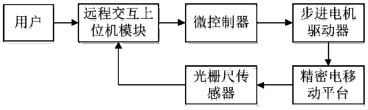
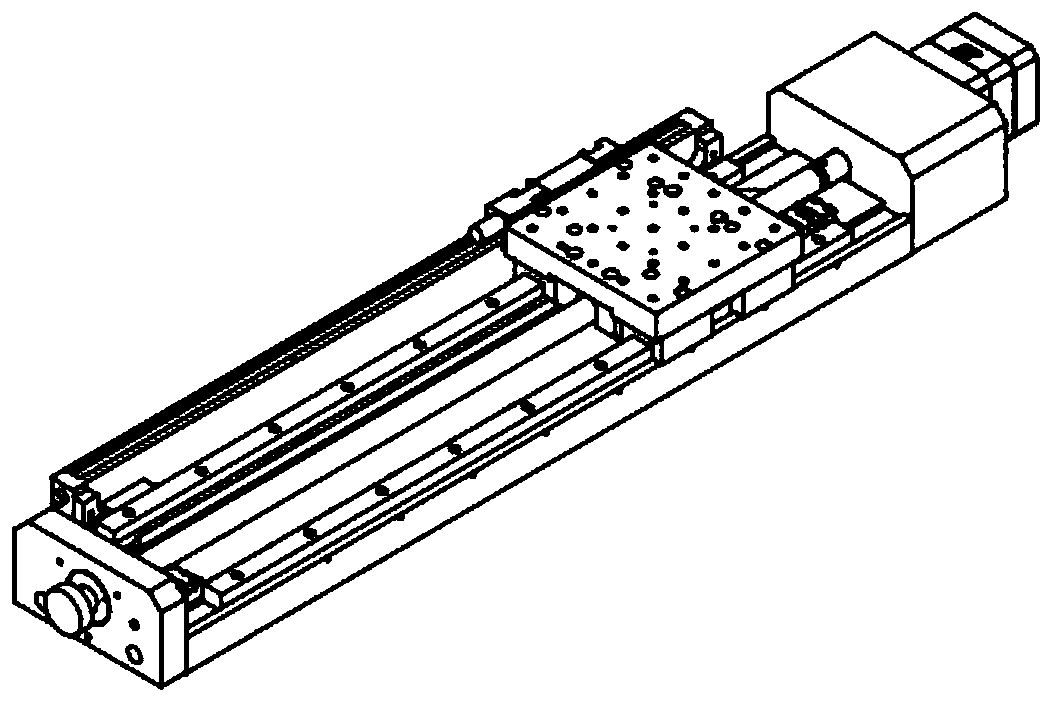
[0047] refer to figure 1 , a numerically controlled automatic microwave imaging system provided by an embodiment of the present invention, comprising: a first sagittal biconvex lens 1, a first plano-convex lens 2, a first concave-convex lens 3, a second concave-convex lens 4, a second plano-convex lens 5, The second sagittal double-convex lens 6 and precision displacement control system;
[0048] The first sagittal biconvex lens 1, the first plano-convex lens 2, the first concave-convex lens 3, the second concave-convex lens 4, the second plano-convex lens 5 and the second sagittal biconvex lens 6...
PUM
| Property | Measurement | Unit |
|---|---|---|
| Center thickness | aaaaa | aaaaa |
Abstract
Description
Claims
Application Information