Method for improving transceiver isolation degree of vehicle-borne millimeter wave radar antenna

A millimeter-wave radar, transceiver isolation technology, applied in the direction of antenna, antenna coupling, antenna array, etc., can solve the problem of lack of suppression, the influence of the uncertain shape of the transceiver antenna pattern, and the poor broadband effect. isolation, reducing overall size requirements, avoiding the effect of vertical size

Active Publication Date: 2019-08-09
FAW CAR CO LTD
View PDF8 Cites 9 Cited by
  • Summary
  • Abstract
  • Description
  • Claims
  • Application Information

AI Technical Summary

Problems solved by technology

Second, this structure only suppresses the surface waves between the transmitting and receiving antennas, but hardly suppresses the electromagnetic waves radiated from the antenna space.
Third, the electromagnetic bandgap structure is a resonant structure, which is effective for narrow-band electric frequencies, but not good for broadband
However, the effectiveness of the isolation plate is related to the height of the pr

Method used


Image

  • Method for improving transceiver isolation degree of vehicle-borne millimeter wave radar antenna
  • Method for improving transceiver isolation degree of vehicle-borne millimeter wave radar antenna
  • Method for improving transceiver isolation degree of vehicle-borne millimeter wave radar antenna

Examples


Embodiment Construction

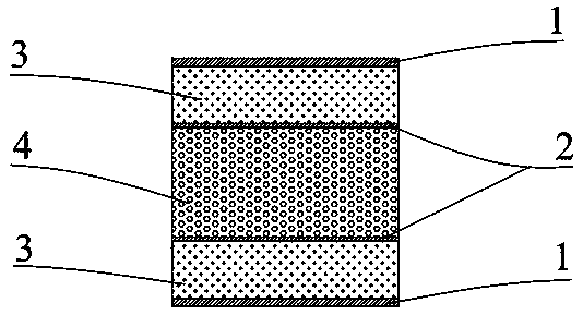
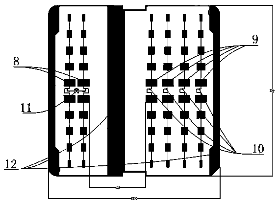
[0025] like image 3 As shown, the overall size of the radar antenna array is Dx*Dy: 73mm*73mm, including one transmitting antenna 8 and four independent receiving antennas 9 . The entire antenna array is attached to the antenna copper clad layer 1, such as figure 1 shown;

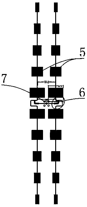
[0026] like figure 2 As shown, the microstrip array antenna 8 adopts the form of two columns of microstrip patch antennas 5 fed in series with 10 elements each, and the feed amplitude of each antenna is controlled by adjusting the patch size perpendicular to the vertical direction of the feed line to form Taylor amplitude weighting, resulting in a 25dB sidelobe radiation pattern.

[0027] The 10-element antenna feed point 10 in each row is located between the fifth unit and the sixth unit. The antenna feed point 10 should meet the requirements of reaching the fifth unit and the phase of the sixth unit. The phase of the operating frequency is 180°. The structure See figure 2 The antenna feed structur...


PUM

PropertyMeasurementUnit
Thicknessaaaaaaaaaa
Thicknessaaaaaaaaaa
Thicknessaaaaaaaaaa

Abstract

The invention relates to a method for improving the transceiver isolation degree of a vehicle-borne millimeter wave radar antenna. According to the method, the isolation degree of transceiver antennasis effectively improved by controlling the radiation levels of receiving and transmitting antenna array patterns in airspaces near plus or minus 90 degrees. By adopting multiple columns of receivingand transmitting antennas, the widths of antenna radiating patches in the direction of a transmitting and receiving array are simultaneously controlled, and the coupling on a spatial radiation path ofthe transmitting and receiving antennas is effectively controlled. When a single-column form is employed by receiving and transmitting, the isolation degree of the transceiver antennas is about 35dBunder the same spacing condition, the widths of the transmitting antenna patches in the direction of the array is adjusted, and so that the isolation degree of the transceiver antennas is increased toabout 55dB.

Description

technical field [0001] The invention belongs to the technical field of radar and automobile electronics, and relates to a method for improving the transceiver isolation of a vehicle-mounted millimeter-wave radar antenna. Background technique [0002] The safe and intelligent driving of automobiles is a hotspot in the field of automotive electronics. The core device is the radar sensor, and the millimeter wave radar has obvious advantages over other forms of sensors such as ultrasonic, infrared, laser, etc., including: easy to achieve higher Excellent range resolution, no range blind zone, low transmit power, not affected by weather, etc. Therefore, millimeter wave radar has also become the main sensor form of automobile collision avoidance. [0003] At present, the working frequency bands of vehicle-mounted millimeter-wave radars are allocated to 24GHz and 77GHz. The existing standard multi-function chip can realize the functions of radar radio frequency and digital part. ...

Claims


Application Information

Patent Timeline
IPC IPC(8): H01Q1/52H01Q1/32H01Q1/38H01Q1/48H01Q21/00H01Q21/12H01Q21/28
CPCH01Q1/3233H01Q1/38H01Q1/48H01Q1/525H01Q21/0006H01Q21/12H01Q21/28
Inventor 王亮马文峰节忠海白一迪雷凯郑岩杨冉王瑞林王瑞琳李成浩黄晓慧赵一张诗宇
Owner FAW CAR CO LTD
Why Eureka
Try Eureka