Centrifugal reagent disk

A reagent disc and centrifugal technology, applied in the field of centrifugal reagent discs, can solve the problems of high device cost, complicated device structure, difficult solid-liquid separation technology, etc.

Pending Publication Date: 2019-08-13
DONGGUAN HEC MEDICAL INTELLIGENT DEVICE R&D CO LTD
View PDF1 Cites 0 Cited by
  • Summary
  • Abstract
  • Description
  • Claims
  • Application Information

AI Technical Summary

Problems solved by technology

However, in microfluidic chips, it is difficult for us to use conventional solid-liquid separation techniques such as filtration, centrifugation, etc.
Even if magnetic or magnetizable magnetic beads are used to make solid-liquid separation relatively convenient, we need to provide an external control device with magnetism, which will cause complex structure and high cost of the device, and we also Additional effects from magnetic controls need to be considered

Method used


Image

  • Centrifugal reagent disk
  • Centrifugal reagent disk
  • Centrifugal reagent disk

Examples


Embodiment 1

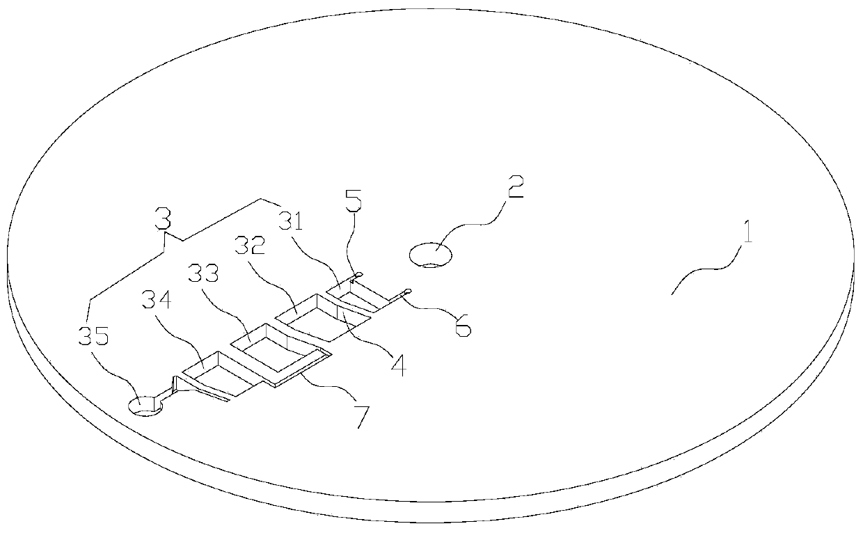
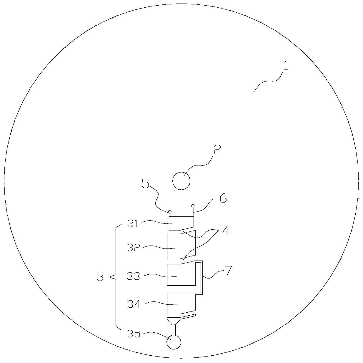
[0088] like Figure 1 to Figure 2As shown, it is a schematic structural diagram of a centrifugal reagent disc in the present invention. The centrifugal reagent disc includes a base plate 1, and the base plate 1 has a rotation center 2. In this embodiment, the base plate 1 is disc-shaped, and the center of the base plate 1 is provided with a Central hole, in this embodiment, the central hole is the rotation center 2 of the substrate, and the centrifugal reagent disc can be installed on the centrifugal device (not shown) through the central hole, and the substrate 1 is made of cycloolefin copolymer (COC / COP) The base material is obtained by injection molding.

[0089] The substrate 1 includes at least one set of test units (only one set of test units is shown in the diagram of this embodiment). The test unit includes at least two chambers 3 and a weir structure 4 arranged between adjacent chambers 3. Valves are arranged on the weir structure 4; The closest chamber 3 is a proxi...

Embodiment 2

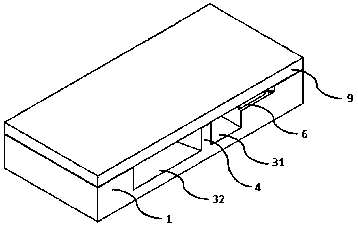
[0098] like Figure 8 to Figure 9 As shown, it is a schematic structural diagram of another centrifugal reagent disc in the present invention. This embodiment is a further improvement on the basis of Embodiment 1. As an improvement of this embodiment, this embodiment is different from Embodiment 1. The difference is that: the first pre-embedded chamber 32 is provided with an exhaust channel 6, and the position of the film 9 corresponding to the top of the exhaust channel 6 has a color mark for subsequent use; Store with lyophilized reagent pellets III.

[0099] When a test needs to be performed, use a sharp tool such as a syringe needle to pierce the film 9 with color marks at the top of the sampling channel 5 and the top of the exhaust channel 6, and then add liquid to the sample chamber 31 sample. By increasing the rotational speed of the substrate 1 fixed on the centrifugal device, the sample can enter the first pre-embedded chamber 31 to mix and react with the liquid rea...

Embodiment 3

[0101] like Figure 10 As shown, it is a schematic structural diagram of a centrifugal reagent disc in the present invention. This embodiment is a further improvement on the basis of Embodiment 1. As an improvement of this embodiment, the differences between this embodiment and Embodiment 1 The location is: the second pre-embedded chamber 33 is provided with an exhaust channel 6, and the position of the film corresponding to the top of the exhaust channel 6 has a color mark for subsequent use. The first pre-embedded chamber 32 and A bypass channel 7 is provided between the third pre-embedded chambers 34; freeze-dried reagent balls are stored in advance in the first pre-embedded chamber 32; liquid reagents are pre-stored in the second pre-embedded chamber 33; Freeze-dried reagent balls are pre-stored in the chamber 34. Second, liquid reagents are pre-stored in the detection chamber 35.

[0102] When a test needs to be performed, use a sharp tool such as a syringe needle to pie...


PUM


Abstract

The invention provides a centrifugal reagent disk. The centrifugal reagent disk comprises a substrate, wherein the substrate is provided with a rotating center and comprises at least one group of testunits, each test unit comprises at least two cavities and a weir structure arranged between the adjacent cavities, and a valve is arranged on each weir structure; the distances from the cavities to the rotation center are not equal, the cavity close to the rotation center is a near-end cavity, the cavity far away from the rotation center is a far-end cavity, and when the rotation speed of the substrate reaches a preset rotation speed, the valves are opened and the reagent in the near-end cavity is released into the adjacent far-end cavity. The centrifugal reagent disk for pre-embedding reagents can pre-embed various liquid reagents and solid reagents at the same time, can enable the pre-embedded reagents to be released, re-dissolved and / or reacted according to a certain sequence, and hasthe advantages of a simple structure, easiness in implementation, low manufacturing cost and the like.

Description

technical field [0001] The invention relates to the technical field of medical devices, in particular to the field of microfluidic chips, in particular to a centrifugal reagent disc. Background technique [0002] Microfluidic chips were originally called "lab-on-a-chip" and "micrototal analytical systems". It is the main platform for the realization of microfluidics. Integrate the basic operation units such as sample preparation, reaction, separation, and detection in the biological, chemical, and medical analysis processes into a micron-scale chip to automatically complete the entire analysis process. The microfluidic chip has the advantages of light size, small amount of samples and reagents, fast reaction speed, large parallel processing and disposable, etc. It has great potential in the fields of biology, chemistry, medicine and so on. It has developed in recent years. It has become a new research field interdisciplinary of biology, chemistry, medicine, fluid, electroni...

Claims


Application Information

Patent Timeline
IPC IPC(8): G01N33/00G01N21/31G01N21/01B01L3/00
CPCG01N33/00G01N21/31G01N21/01B01L3/00
Inventor 陈跃东张意如熊灿顾志鹏刘仁源
Owner DONGGUAN HEC MEDICAL INTELLIGENT DEVICE R&D CO LTD
Why Eureka
Try Eureka