Desulfurization and denitrification device for steel sintering flue gas

A technology for sintering flue gas, desulfurization and denitrification, applied in gas treatment, membrane technology, dispersed particle separation, etc., can solve the problems of urea solution blockage, scouring wear, etc., and achieve the effect of avoiding blockage

Pending Publication Date: 2019-08-16
陈炜健
View PDF10 Cites 0 Cited by
  • Summary
  • Abstract
  • Description
  • Claims
  • Application Information

AI Technical Summary

Problems solved by technology

[0005] Aiming at the deficiencies of the prior art, the present invention provides a steel sintering flue gas desulfurization and denitrification equipment, which is equipped with a turbulent flow heating nozzle to ensure that the urea solution can be sprayed out smoothly, avoiding crystallization, and a buffer refraction device that can absorb silicon dioxide particles. Kinetic ene

Method used


Image

  • Desulfurization and denitrification device for steel sintering flue gas
  • Desulfurization and denitrification device for steel sintering flue gas
  • Desulfurization and denitrification device for steel sintering flue gas

Examples


Embodiment Construction

[0024] The following will clearly and completely describe the technical solutions in the embodiments of the present invention with reference to the accompanying drawings in the embodiments of the present invention. Obviously, the described embodiments are only some, not all, embodiments of the present invention. Based on the embodiments of the present invention, all other embodiments obtained by persons of ordinary skill in the art without making creative efforts belong to the protection scope of the present invention.

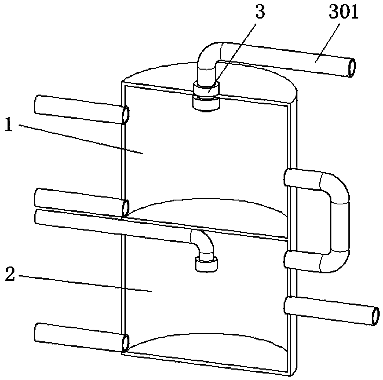
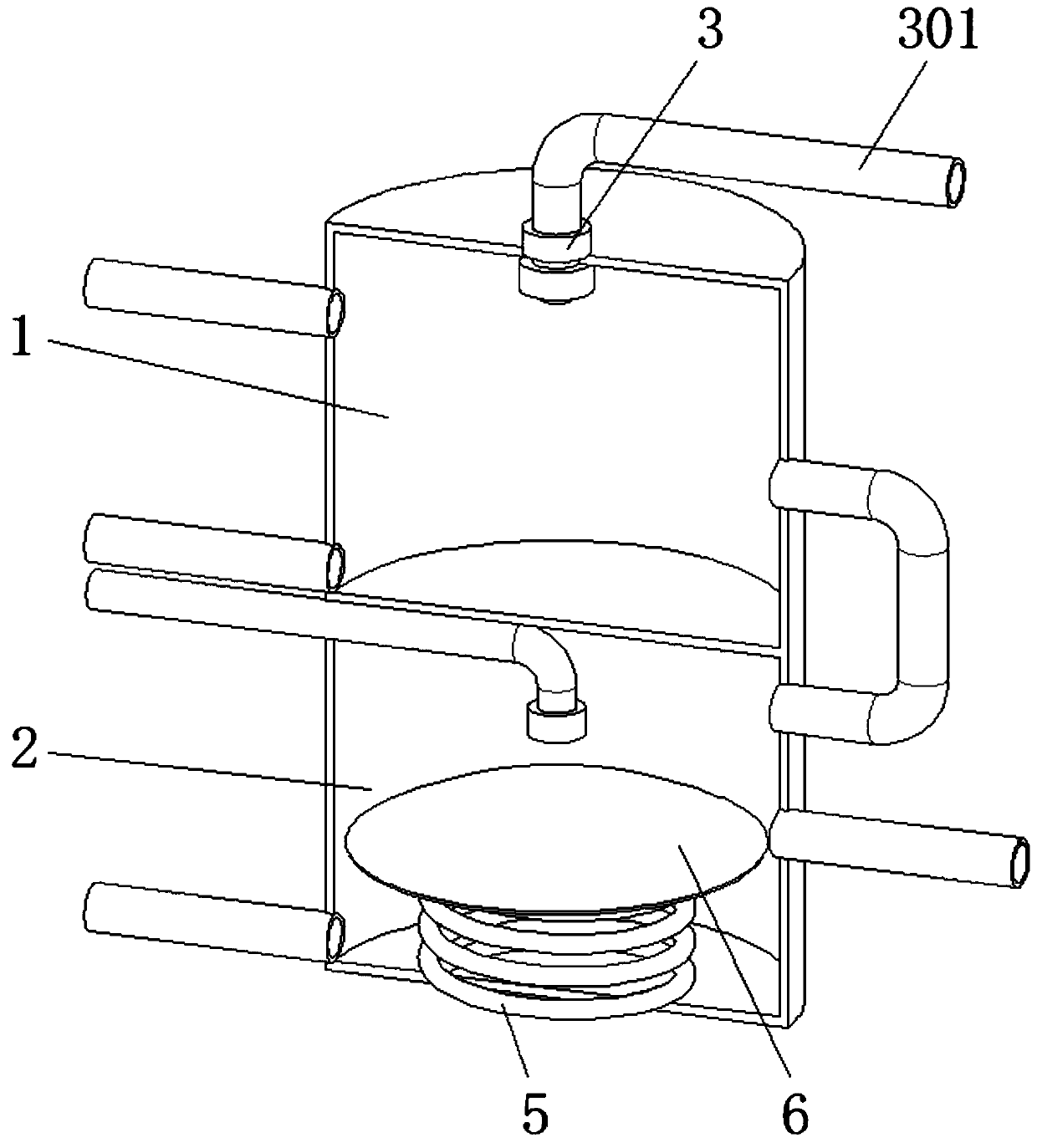
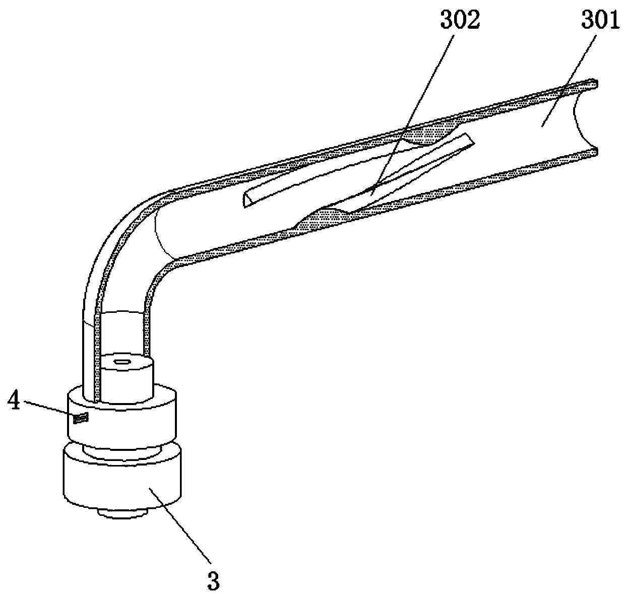
[0025] see Figure 2-5 , a steel sintering flue gas desulfurization and denitrification equipment, comprising a denitrification chamber 1, a desulfurization chamber 2, an atomizing nozzle 3 and a liquid inlet pipe 301, the inner wall of the liquid inlet pipe 301 is fixedly equipped with a spoiler 302, which is used for the urea solution Spoiler, the cross-sectional shape of the spoiler 302 is a solid triangle with a bottom arc, the number of the spoiler 302 is...


PUM


Abstract

The invention relates to the technical field of flue gas desulfurization and denitrification equipment, and discloses a desulfurization and denitrification device for steel sintering flue gas. The device comprises a denitrification chamber, a desulfurization chamber, an atomizing nozzle and a liquid inlet pipe; spoilers are fixedly arranged on the inner wall of the liquid inlet pipe; a cavity is formed in the atomizing nozzle; a through groove is formed in the atomizing nozzle; electric heating wires are fixedly arranged inside the through groove and the cavity; and a spring is fixedly arranged on the bottom surface of the desulfurization chamber. According to the desulfurization and denitrification device for steel sintering flue gas, a urea solution generates turbulence and rotates alongthe surfaces of the spoilers when passing through the spoilers, and the solution forms a vortex-like flow in the liquid inlet pipe, so that separated crystals cannot be attached to the pipe wall, andthen smoothness of the nozzle is ensured. Meanwhile, the urea solution is heated by the electric heating wires when reaching the nozzle, so that the separated crystals are dissolved in the solvent again, and blockage of the nozzle is further avoided.

Description

technical field [0001] The invention relates to the technical field of flue gas desulfurization and denitrification equipment, in particular to a steel sintering flue gas desulfurization and denitrification equipment. Background technique [0002] Flue gas desulfurization and denitrification equipment is a tail gas treatment equipment that removes sulfur dioxide and nitrogen oxides in the flue gas generated after steel sintering. [0003] The structure of common flue gas desulfurization and denitrification equipment is as follows: figure 1 As shown, it includes the denitration chamber and the desulfurization chamber. The tops of the denitration chamber and the desulfurization chamber are equipped with liquid inlet pipes and nozzles. The nozzles on the top of the denitration chamber are used to spray urea solution for denitrification. Since the urea solution enters the liquid inlet pipe from the storage tank During the spraying process, the heat dissipation temperature of th...

Claims


Application Information

Patent Timeline
IPC IPC(8): B01D53/75B01D53/79B01D53/56B01D53/80B01D53/50
CPCB01D53/502B01D53/504B01D53/56B01D53/75B01D53/79B01D53/80B01D2251/2067B01D2251/404B01D2251/606B01D2258/0283
Inventor 不公告发明人
Owner 陈炜健
Why Eureka
Try Eureka