Releasing device for underwater robot and water surface high-speed unmanned boat

A technology of underwater robots and delivery devices, which is applied in transportation and packaging, ships, cargo handling equipment, etc., can solve the problems of large resource consumption and low fault tolerance rate, and achieve the effects of shortening delivery time, reducing accidents and improving work efficiency

Inactive Publication Date: 2019-08-16
HARBIN UNIV OF SCI & TECH
View PDF11 Cites 4 Cited by
  • Summary
  • Abstract
  • Description
  • Claims
  • Application Information

AI Technical Summary

Problems solved by technology

[0003] In order to solve the problem that the existing delivery device consumes a lot of resources and has a low fault tolerance rate in the delivery process, the present invention further provides a delivery device for underwater robots and surface high-speed unmanned boats

Method used


Image

  • Releasing device for underwater robot and water surface high-speed unmanned boat
  • Releasing device for underwater robot and water surface high-speed unmanned boat
  • Releasing device for underwater robot and water surface high-speed unmanned boat

Examples


specific Embodiment approach 1

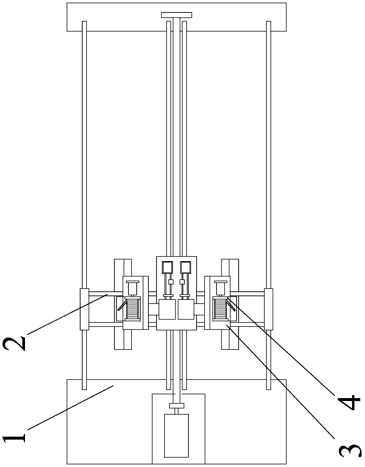
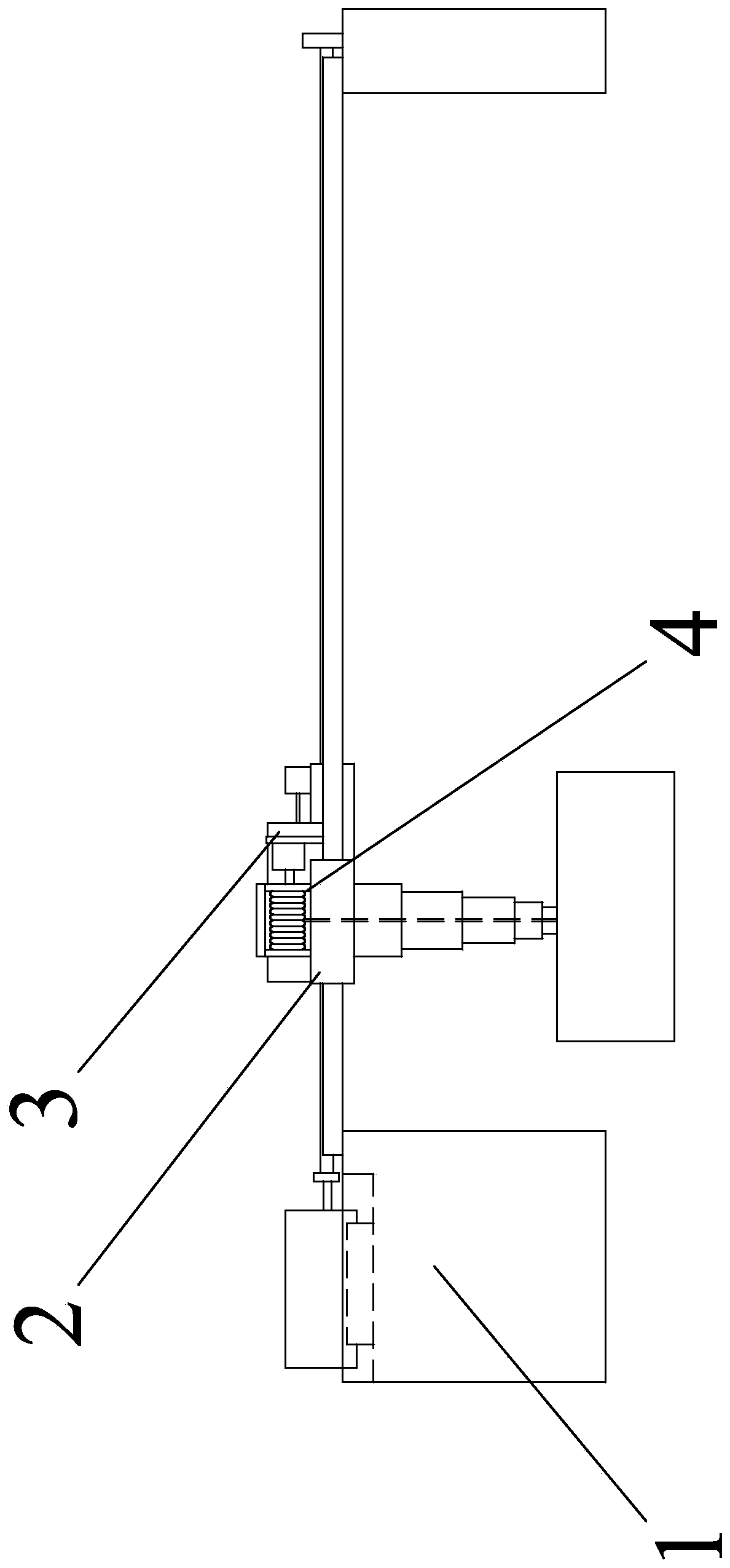
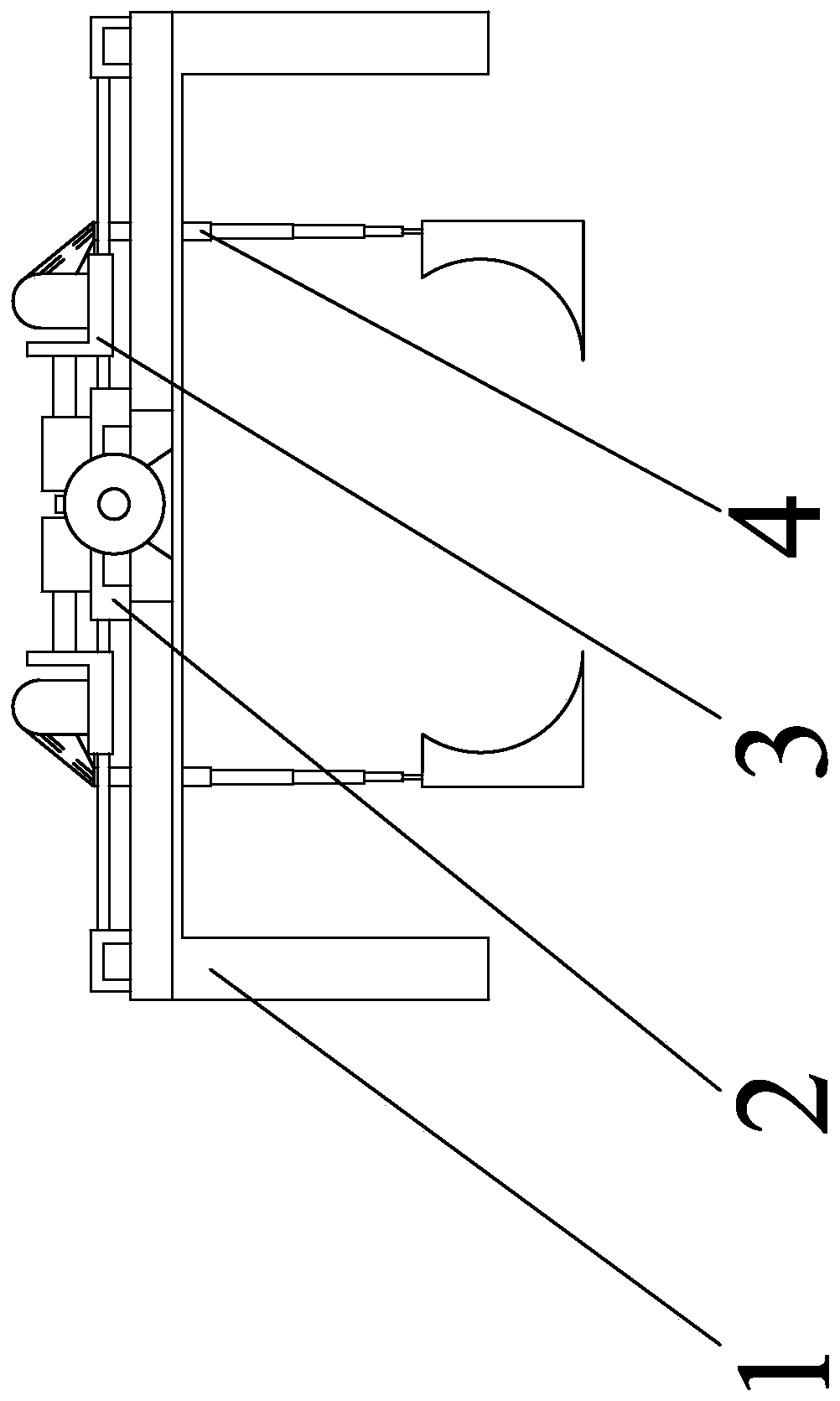
[0031] Specific implementation mode one: combine Figure 1 to Figure 3 Describe this embodiment, in this embodiment, a delivery device for underwater robots and surface high-speed unmanned boats, it includes a support mechanism 1, a workbench 2, two pushing mechanisms 3 and two lowering mechanisms 4;

[0032] The workbench 2 is slidably connected to the support mechanism 1, and two push mechanisms 3 are installed on the workbench 2, and the two push mechanisms 3 are arranged facing away from each other, and each lowering mechanism 4 is fixedly connected to one push mechanism 3.

specific Embodiment approach 2

[0033] Specific implementation mode two: combination Figure 8 Describe this embodiment, the support mechanism 1 in this embodiment includes a main support 1-1, a screw 1-3, an auxiliary support 1-4, a No. 1 motor 1-5, a shaft coupling 1-6, a bearing Bearing seat 1-7 and four slideways 1-2;

[0034] The main support 1-1 and the auxiliary support 1-4 are arranged oppositely, the No. 1 motor 1-5 is fixedly connected on the upper surface of the main support 1-1, and the output end of the No. 1 motor 1-5 faces the auxiliary support 1-4, Bearing seat 1-7 with bearing is fixedly connected on the upper surface of auxiliary support 1-4, and four slideways 1-2 are mutually arranged in parallel on the upper surface of main support 1-1 and auxiliary support 1-4, and each One end of the root slideway 1-2 is fixedly connected with the upper surface of the main support 1-1, and the other end of each slideway 1-2 is fixedly connected with the upper surface of the auxiliary support 1-4, and ...

specific Embodiment approach 3

[0036] Specific implementation mode three: combination Figure 4 Describe this embodiment, the workbench 2 in this embodiment includes a work plate 2-1, two auxiliary slideway groups 2-2 and two auxiliary sliders 2-3;

[0037]Two auxiliary slideway groups 2-2 are respectively arranged on a side wall of the working plate 2-1, and one end of each auxiliary slideway group 2-2 is fixedly connected with a side wall of the working plate 2-1, each The other end of the auxiliary slideway group 2-2 is fixedly connected with the side wall of an auxiliary slide block 2-3, and the lower surface of the working plate 2-1 is provided with two parallel No. 1 slides along the length direction of the working plate 2-1. Slot 2-1-1, the middle part of the end wall of the working plate 2-1 is provided with a threaded through hole 2-1-2, and the lower surface of each auxiliary slider 2-3 is provided with a parallel to the No. 1 chute. No. 2 chute 2-3-1, lead screw 1-3 is set in threaded through ho...


PUM


Abstract

The invention provides a releasing device for an underwater robot and a water surface high-speed unmanned boat, and belongs to the field of releasing devices. The releasing device is mainly used for solving the problems that a releasing device consumes large resources, and the error-tolerant rate is low in the releasing process. The releasing device comprises a supporting mechanism, a working table, two pushing mechanisms and two downward-running mechanisms; and the working table is slidably connected to the supporting mechanism, the two pushing mechanisms are mounted on the working table andarranged back to back, and each downward-running mechanism is fixedly connected to one pushing mechanism. The releasing device is mainly applied to transporting of the underwater robot and the water surface high-speed unmanned boat from a salvage ship into water or onto the water surface.

Description

technical field [0001] The invention belongs to the field of delivery devices, in particular to a delivery device for underwater robots and surface high-speed unmanned boats. Background technique [0002] Underwater robots and surface high-speed unmanned boats are relatively advanced unmanned controllers, most of which are used for ocean surveys, marine accident search and rescue, ocean exploration and other activities. The development of the field of high-speed unmanned boats has also gradually matured. Many underwater robots and surface high-speed unmanned boats have come out one after another. The complex linearity of the surface shells of such underwater robots and surface high-speed unmanned boats is more suitable for Or adapt to the flow of seawater when working on the water surface, so as to reduce the damage to the shell in the complex environment when working underwater or on the water surface, but this improvement has brought great benefits to the launch of underwa...

Claims


Application Information

Patent Timeline
Patent Type & Authority Applications(China)
IPC IPC(8): B63B27/16
CPCB63B27/16B63B2027/165
Inventor 尹莉莉马超李鹏
Owner HARBIN UNIV OF SCI & TECH
Why Eureka
Try Eureka