Three-way control valve structure

A three-way control valve and valve body technology, applied in multi-way valves, valve details, valve devices, etc., can solve the problems of single structure, unsatisfactory use effect and service life, damaged valve body, etc., and achieve good sealing effect. , good economic use value, prolong the service life effect

Pending Publication Date: 2019-08-16
WUXI XHK VALVE
View PDF0 Cites 1 Cited by
  • Summary
  • Abstract
  • Description
  • Claims
  • Application Information

AI Technical Summary

Problems solved by technology

[0002] At present, the three-way diversion (combination) control valve is the most commonly used valve in the pipeline of the automatic control system, but the traditional three-way diversion (combination) control valve has a single structure, after the valve body is impacted by the fluid for a long time, the valve body will be damaged. The damage is more serious, the sealing performance is also significantly reduced, and there is a large noise during use, and the functions of cutting off and regulating the flow cannot be realized at the same time. Therefore, the use effect and service life of the traditional three-way diversion (combination) control valve are not ideal

Method used


Image

  • Three-way control valve structure
  • Three-way control valve structure
  • Three-way control valve structure

Examples


Embodiment 1

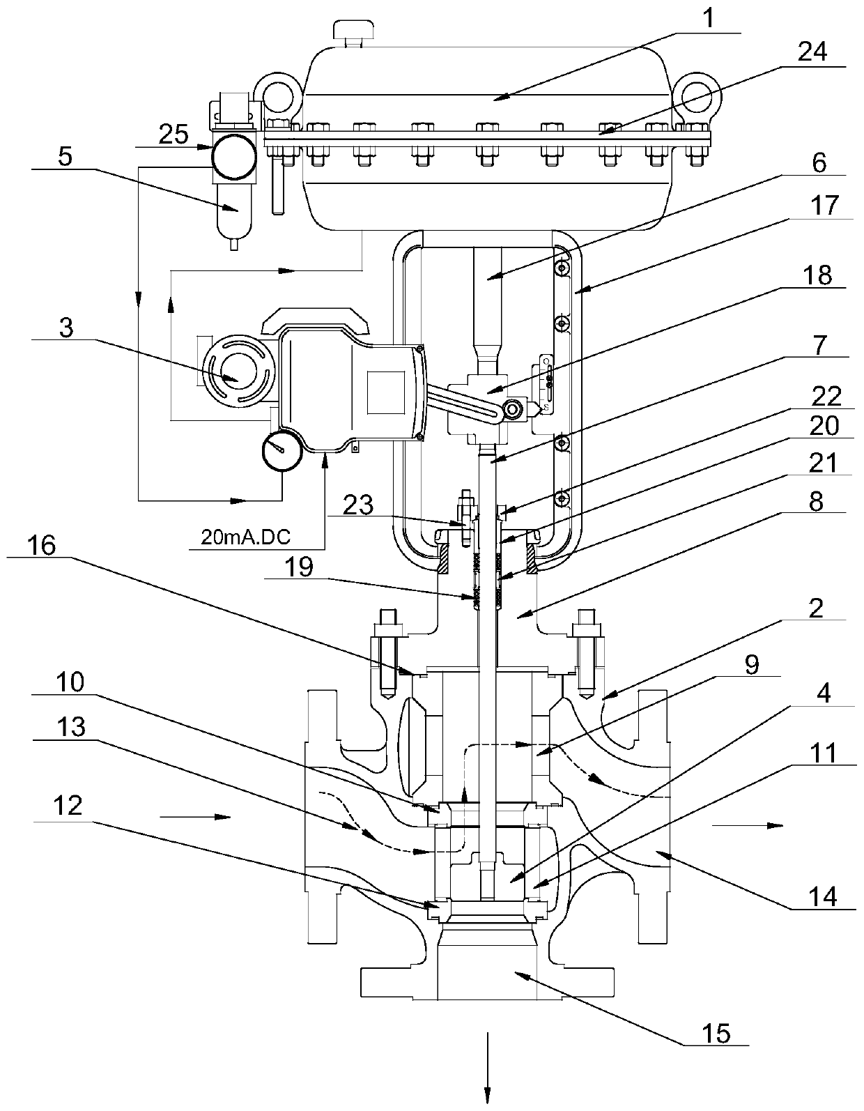
[0019] Such as Figure 1 ~ Figure 3 As shown, the present invention includes a valve body 1, an actuator 2 and a locator 3 connected to the actuator 2. The valve body 1 is a four-way structure, the valve body 1 is provided with a valve core 4, and the input end of the actuator 2 is provided There is a pressure reducing valve 5, the output end is connected with a push rod 6, the push rod 6 is connected with the valve stem 7, the lower end of the valve stem 7 passes through the valve cover 8 and then extends into the valve body 1 to connect with the valve core 4, the valve cover 8 is fixedly connected with the valve body 1, and the valve body 1 is provided with a balance cylinder 9 and an upper valve seat 10, a sleeve 11, and a lower valve seat 12 with the same inner diameter in sequence from top to bottom, and an upper valve seat 10, a sleeve 11, and a lower valve seat 12. The valve seat 12 is set at the flow port of the valve body 1, the sleeve 11 is sleeved on the outer wall ...

Embodiment 2

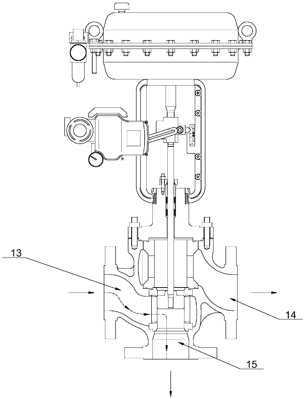
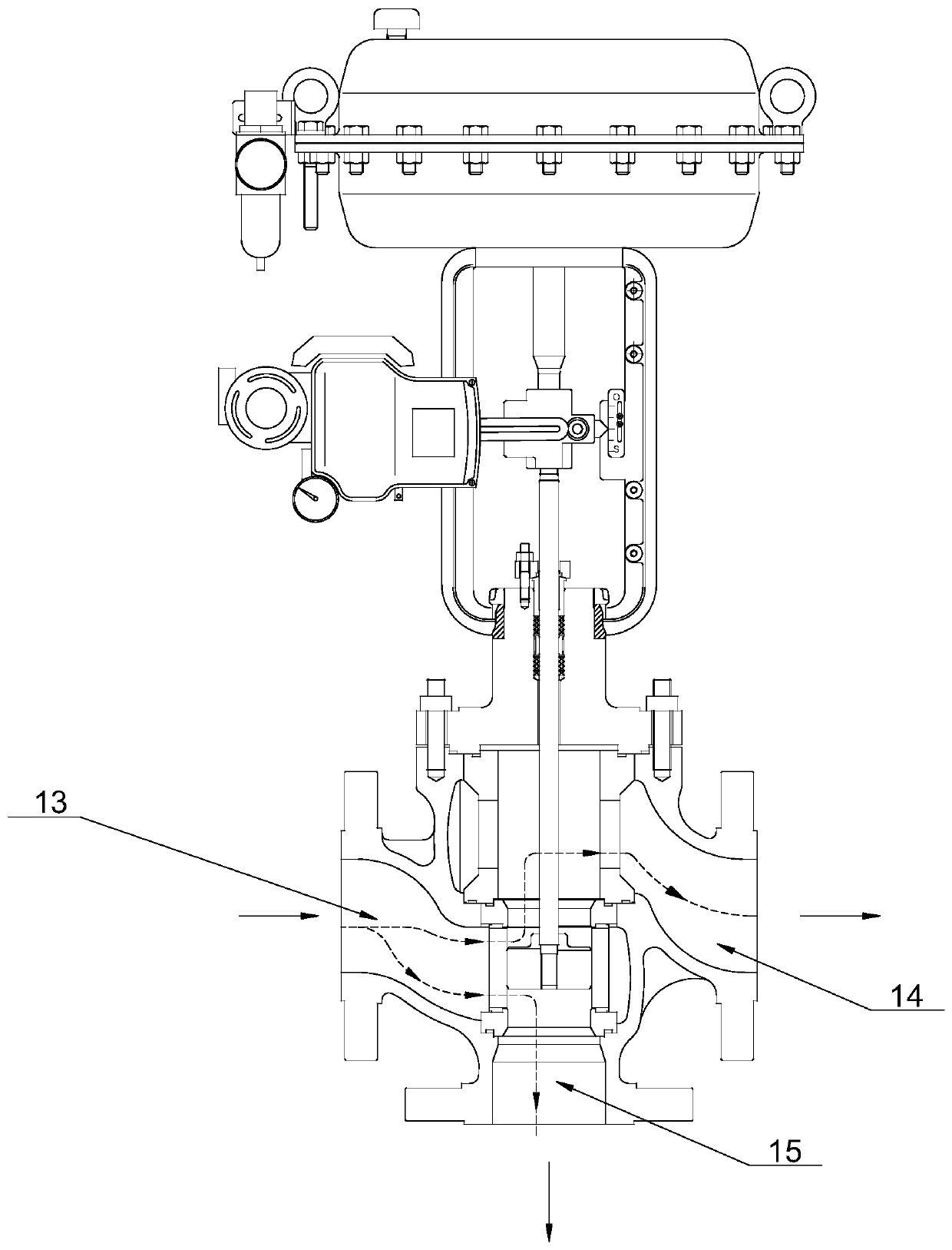
[0030] When there is a signal, the actuator 2 raises the valve core 4 under the action of compressed air, and the valve core 4 is in close contact with the sealing surface of the upper valve seat 10, thus closing the flow port II14 and opening the flow port I13, flow port Ⅲ15, such as Figure 5 As shown; when there is no signal, the actuator 2 pushes the spool 4 downward by the elastic force of its own spring return, so that the spool 4 descends, and the spool 4 is in close contact with the sealing surface of the lower valve seat 12, thereby closing the flow port III15, The circulation port Ⅰ13 and the circulation port Ⅱ14 are opened, such as Figure 4 As shown; where the spool 4 is under the action of the positioner 3, the spool 4 can be placed at different heights of the window of the sleeve 11, and the purpose of adjusting the fluid flow can be played. At half the height of the window, the fluid medium is in a confluent state, such as Image 6 shown.

[0031] Figure 4 ...


PUM


Abstract

The invention provides a three-way control valve structure. The sealing effect is good, the using effect under different working conditions can be achieved, and the service life can be prolonged. Thethree-way control valve structure comprises a valve body, an executing mechanism and a positioner connected with the executing mechanism; the valve body is of a four-way structure, and a valve elementis arranged in the valve body; a pressure reducing valve is arranged at the input end of the executing mechanism, a pushing rod is connected to the output end of the executing mechanism, the pushingrod is connected with a valve rod, the lower end of the valve rod penetrates through a valve deck and then stretch into the valve body to be connected with the valve element, and the valve deck is fixedly connected with the valve body; and a balance cylinder and an upper valve seat, a sleeve and a lower valve seat which have the same inner diameter are sequentially arranged in the valve body fromtop to bottom, the upper valve seat, the sleeve and the lower valve seat are arranged at a circulating port of the valve body, the sleeve is arranged on the outer wall of the valve element in a sleeving mode, a clearance is reserved between the sleeve and the valve element, the length of the valve element is smaller than that of the sleeve, and the sleeve is provided with a flow hole.

Description

technical field [0001] The invention relates to the technical field of valves, in particular to a three-way control valve structure. Background technique [0002] At present, the three-way diversion (combination) control valve is the most commonly used valve in the pipeline of the automatic control system, but the traditional three-way diversion (combination) control valve has a single structure, after the valve body is impacted by the fluid for a long time, the valve body will be damaged. The damage is more serious, the sealing performance is also significantly reduced, and there is a large noise during use, and the functions of cutting off and regulating the flow cannot be realized at the same time. Therefore, the use effect and service life of the traditional three-way diversion (combination) control valve Neither is ideal. Contents of the invention [0003] In view of the above problems, the present invention provides a three-way control valve structure, which has a g...

Claims


Application Information

Patent Timeline
Patent Type & Authority Applications(China)
IPC IPC(8): F16K11/044F16K31/128
CPCF16K11/044F16K31/128
Inventor 朱粉华邹喜范小娟
Owner WUXI XHK VALVE
Why Eureka
Try Eureka