
Leakage positioning method based on ultrasonic wave speed change

A positioning method and ultrasonic technology, which can be used in the testing of fluid tightness, the testing of machine/structural components, and the measurement of the acceleration and deceleration rates of fluids. Use scope and other issues to achieve the effect of improving feasibility and applicability, simple method and easy implementation

Inactive Publication Date: 2019-08-16
LIAONING UNIVERSITY OF PETROLEUM AND CHEMICAL TECHNOLOGY
View PDF7 Cites 5 Cited by
  • Summary
  • Abstract
  • Description
  • Claims
  • Application Information

AI Technical Summary

Problems solved by technology

The specific performance is: install the sensor at the first and last station of the pipeline, measure the time difference between the leakage sound wave reaching the first and last station of the pipeline, so as to locate the leak point, and install the pressure transmitter or infrasonic wave sensor by using the original interface of the pipeline or punching holes on the pipeline for installation , which invisibly increases the safety risk of pipeline operation and reduces the application range of negative pressure wave method and infrasonic wave method

Method used


Image

  • Leakage positioning method based on ultrasonic wave speed change
  • Leakage positioning method based on ultrasonic wave speed change
  • Leakage positioning method based on ultrasonic wave speed change

Examples


Embodiment Construction

[0031] The application principle of the present invention will be further described below in conjunction with the accompanying drawings and specific embodiments.

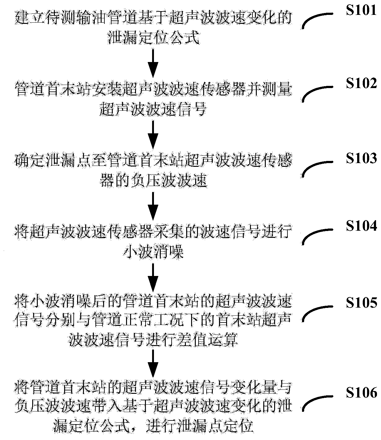
[0032] Such as figure 1 As shown, the leakage location method based on the change of ultrasonic wave velocity provided by the present invention includes the following steps:

[0033] Step 1 S101: Establishing a leak location formula based on ultrasonic wave changes of the oil pipeline to be tested;

[0034] Step 2 S102: installing an ultrasonic wave velocity sensor at the first and last station of the oil pipeline to be tested and collecting ultrasonic wave velocity signals;

[0035] Step 3 S103: Determine the negative pressure wave velocity from the leak point to the ultrasonic wave velocity sensor at the first and last stations of the pipeline;

[0036] Step 4 S104: Perform wavelet de-noising on the wave velocity signal collected by the ultrasonic wave velocity sensor;

[0037] Step 5 S105: Perform difference c...


PUM


Abstract

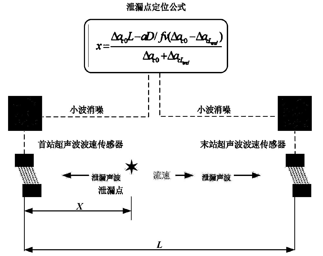
The invention discloses a leakage positioning method based on ultrasonic wave speed change. The method comprises the following steps: a leakage positioning formula based on ultrasonic wave change of an oil conveying pipe to be detected is built; ultrasonic wave speed sensors are mounted at head and tail stations of the oil conveying pipe to be detected for acquiring ultrasonic wave speed signals;a negative-pressure wave speed from a leakage point to the ultrasonic wave speed sensors at the head and tail stations of the pipe is determined; the wavelet noise removal is performed on the wave speed signals acquired by the ultrasonic wave speed sensors; difference values between the ultrasonic wave speed signals at the head and tail stations of the pipe after the wavelet noise removal and theultrasonic wave speed signals at the head and tail stations of the pipe under normal working conditions are calculated; and ultrasonic wave speed signal change quantities at the head and tail stationsof the pipe and the negative-pressure wave speed are introduced in the leakage positioning formula based on the ultrasonic wave speed change to position the leakage point. The leakage positioning method based on the ultrasonic wave speed change prevents the problem of positioning of the leakage point by using the time difference of leaked sound waves reaching the head and tail stations of the pipe; and when the leakage point of the pipe is positioned, the leakage point is positioned by using the ultrasonic wave speed change quantities of the head and tail stations of the pipe, so that the nondestructive installation on the pipe is achieved, and the feasibility and the applicability of the leakage detection by using the ultrasonic sensors are improved.

Description

[0001] Technical field: [0002] The invention belongs to the technical field of ultrasonic leakage monitoring of oil pipelines, and in particular relates to a leakage location method based on changes in ultrasonic wave velocity. [0003] Background technique: [0004] At present, there are many leakage monitoring methods used in oil pipelines. Among them, the ultrasonic leakage detection method has many advantages compared with the traditional negative pressure wave method, flow balance method, and transient model method: such as no need to open holes in the pipeline, The on-site construction of the pipeline is convenient, the location of the leakage point is high, and the false alarm rate is low; the measurement is the change of the ultrasonic wave velocity at the first and last stations of the pipeline, and the non-destructive testing does not destroy the internal pressure distribution of the pipeline. [0005] In the research of leakage detection and location technology for...

Claims


Application Information

Patent Timeline
Patent Type & Authority Applications(China)
IPC IPC(8): F17D5/06G01M3/28
CPCF17D5/06G01M3/2807
Inventor 郎宪明郭颖高文帅
Owner LIAONING UNIVERSITY OF PETROLEUM AND CHEMICAL TECHNOLOGY
Learn More