
Light source heat insulation structure

A light source and heat shield technology, applied in the field of optics, can solve problems such as unsatisfactory heat insulation effects of lighting equipment

Active Publication Date: 2020-12-11
广州市焦汇光电科技有限公司
View PDF9 Cites 0 Cited by
  • Summary
  • Abstract
  • Description
  • Claims
  • Application Information

AI Technical Summary

Problems solved by technology

[0004] Based on this, it is necessary to address the problem of unsatisfactory heat insulation effect of lighting equipment, and provide a light source heat insulation structure that can reasonably solve this problem

Method used


Image

  • Light source heat insulation structure
  • Light source heat insulation structure

Examples


Embodiment Construction

[0022] In order to make the object, technical solution and advantages of the present invention clearer, the present invention will be further described in detail below in conjunction with the accompanying drawings and embodiments. It should be understood that the specific embodiments described here are only used to explain the present invention, not to limit the present invention.

[0023] It should be noted that all technical and scientific terms used herein have the same meaning as commonly understood by those skilled in the technical field of the present invention. The terms used herein in the description of the present invention are for the purpose of describing specific embodiments only, and are not intended to limit the present invention. As used herein, the term "and / or" includes any and all combinations of one or more of the associated listed items.

[0024] In practical applications, such as metal halide bulbs, gas discharge bulb light sources and other application s...


PUM


Abstract

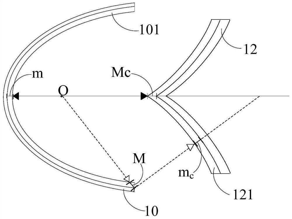
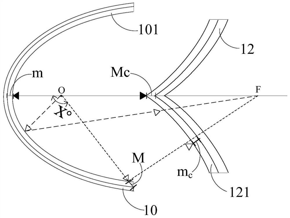
The invention relates to a light source heat insulation structure. The structure comprises a reflection bowl and a curved surface heat insulation piece which are sequentially arranged; the reflectivebowl and the curved surface heat insulation piece are located on the two sides of the optical axis of the light source O; a high-reflecting film is plated on the reflective bowl, and an antireflectionfilm is plated on the curved surface heat insulation piece; the vertical incident light of the light source O generates a first optical path minimum value m after passing through the high-reflectingfilm, and generates a second optical path maximum value Mc after passing through the antireflection film; the maximum-incident-angle light of the light source O generates a first optical path maximumvalue M after passing through the high-reflecting film, and generates a second optical path minimum value mc after passing through the antireflection film; and the sum of the first optical path maximum value M and the second optical path minimum value mc is equal to the sum of the second optical path maximum value Mc and the first optical path the minimum value m. According to the scheme, the light energy loss can be reduced, the heat-emitting light can be prevented from entering the light path structure, the damage rate of optical devices is reduced, and the heat insulation effect of the light source heat insulation structure is improved.

Description

technical field [0001] The invention relates to the field of optics, in particular to a light source heat insulation structure. Background technique [0002] At present, lighting equipment has become an indispensable daily necessities in people's life. [0003] Traditional lighting equipment is usually composed of metal halide bulbs or gas discharge bulbs, but due to the working characteristics of metal halide bulbs and gas discharge bulbs, the light emitted by conventional types of metal halide bulbs and gas discharge bulbs contains a lot of infrared light And ultraviolet light, while infrared light and ultraviolet light will generate a lot of heat, if the infrared light and ultraviolet light cannot be effectively blocked from entering other optical systems, it will cause damage to the lighting equipment. To solve such problems, it is usually to use reflective bowl coating or install heat shields to block infrared light and ultraviolet light from entering the light path. H...

Claims


Application Information

Patent Timeline
Patent Type & Authority Patents(China)
IPC IPC(8): G02B6/00
CPCF21V7/06F21V9/04F21V9/06F21V29/15F21V7/28
Inventor 尹勇健陈卫洪
Owner 广州市焦汇光电科技有限公司
Learn More