Microwave sensor for measuring dielectric constant and magnetic conductivity of magnetic medium material

A technology of microwave sensor and dielectric constant, applied in the field of microwave, can solve the problems that it is difficult to measure the dielectric constant and magnetic permeability of magnetic medium materials, it cannot measure the dielectric constant and magnetic permeability at the same time, and the sensor has a single function. Achieve the effects of high sensitivity, high sensitivity and Q value, and ensure accuracy

Active Publication Date: 2019-08-16
HANGZHOU DIANZI UNIV
View PDF5 Cites 8 Cited by
  • Summary
  • Abstract
  • Description
  • Claims
  • Application Information

AI Technical Summary

Problems solved by technology

Therefore, the measurement of the permittivity and permeability of the magnetic medium material is independent of each other, and the sensor has a single function, which can only be aimed at the measurement of a certain parameter, and cannot measure the permittivity and permeability at the same time
In addition, the existing resonant sensors have a disadvantage, that is, the resolution will decrease with the expansion of the measurement range
That is, measurements must be made in a narrow band, which makes it difficult to measure magnetic media materials with high permittivity and permeability

Method used


Image

  • Microwave sensor for measuring dielectric constant and magnetic conductivity of magnetic medium material
  • Microwave sensor for measuring dielectric constant and magnetic conductivity of magnetic medium material
  • Microwave sensor for measuring dielectric constant and magnetic conductivity of magnetic medium material

Examples


Embodiment Construction

[0026] The present invention will be described in further detail below with specific embodiments in conjunction with the accompanying drawings.

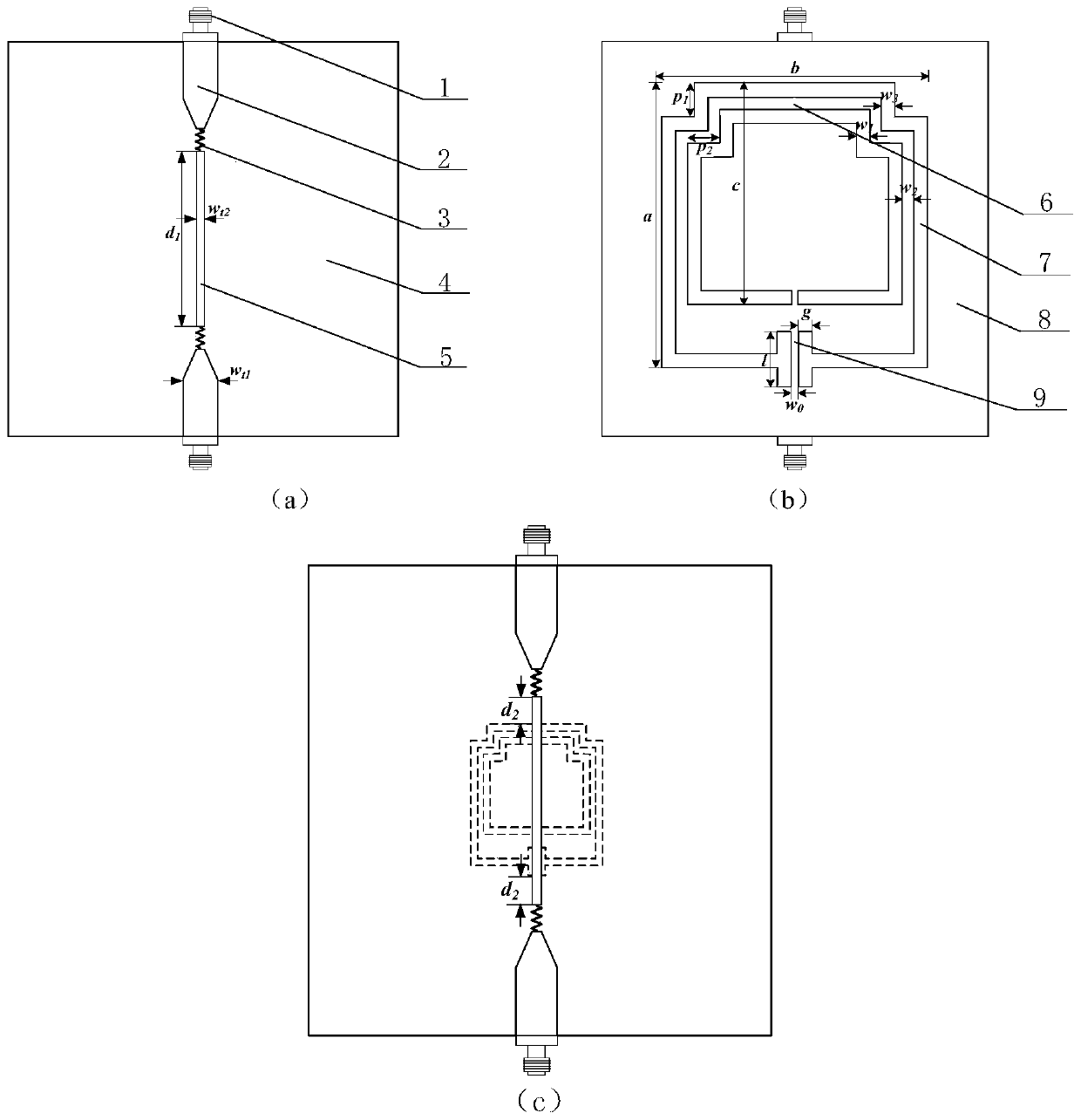
[0027] Such as figure 1 Shown is the structure schematic diagram of the present invention, and the sensor of the present invention comprises the CSRR slot ring 7 that top layer microstrip line, middle layer PCB board 4, bottom metal sheet 8 are etched; Top layer microstrip line includes two sections of microstrip line I2 and A section of microstrip line Ⅱ5, a section of the first microstrip line Ⅰ and microstrip line Ⅱ5, and the other section of the first microstrip line Ⅰ and microstrip line Ⅱ5 are respectively welded through two 50Ω resistors 3, and the microstrip line Ⅰ2 is extended to feed The long pin is used to connect the SMA connector 1; the microstrip line II 5 is coupled to the underlying CSRR slot ring 7;

[0028] The grooved metal CSRR structure is composed of inner and outer groove rings; the inner and outer groove ring...


PUM


Abstract

The invention discloses a microwave sensor for measuring a dielectric constant and magnetic conductivity of a magnetic medium material. The microwave sensor comprises a microstrip line structure, a medium layer, a metal sheet and a slotted metal CSRR (complementary split-ring resonator) structure from a top layer to a bottom layer. The slotted metal CSRR structure is composed of an inner slot ringand an outer slot ring, wherein each of the inner slot ring and the outer slot ring is provided with an opening, and facing directions of the openings are identical; two opposite right angles of theopening of the inner slot ring and two opposite right angles of the opening of the outer slot ring are all folded inwards in an alignment mode, and the opening of the outer slot ring extends towards the inside and outside of the outer slot ring to form channels; the part between the channels of the opening of the outer slot ring is a region with maximum magnetic field intensity, and the region isused to contain a to-be-detected sample for measuring the magnetic conductivity of the sample; and the part between the channels, where the two inwards-folded right angles of the inner slot ring and the two inwards-folded right angles of the outer slot ring are connected, is a region with maximum electric field intensity, and the region is used to contain the to-be-detected sample for measuring the dielectric constant of the sample. According to the microwave sensor, the dielectric constant and the magnetic conductivity can be measured simultaneously in different regions of the same sensor, the sensor has extremely high sensitivity and Q value, and the accuracy of measurement is guaranteed.

Description

technical field [0001] The invention belongs to the field of microwave technology, relates to a microstrip excitation sensor, in particular to a complementary split-ring resonator (complementary split-ring resonator—CSRR)-based sensor for measuring the permittivity and permeability of magnetic media materials Miniaturized microwave sensors. Background technique [0002] With the rapid development of microwave technology in many industries (such as military, medical, food, chemical and meteorology, etc.), various types of radio frequency microwave devices have been gradually developed and applied. The electromagnetic properties of magnetic media materials greatly affect the performance parameters of equipment devices, so the research on the electromagnetic properties of magnetic media materials is very important. [0003] The electromagnetic properties of magnetic media materials are characterized by three parameters: permittivity ε, magnetic permeability μ, and electrical c...

Claims


Application Information

Patent Timeline
Patent Type & Authority Applications(China)
IPC IPC(8): G01R27/26G01R33/12
CPCG01R27/2623G01R33/1223
Inventor 甘宏祎赵文生徐魁文王高峰
Owner HANGZHOU DIANZI UNIV
Why Eureka
Try Eureka