
Optimal dispatching method for virtual power plant containing photothermal power station

A technology of photothermal power plants and virtual power plants, applied in photovoltaic power generation, wind power generation, electrical components, etc., can solve the problem of limiting the ability of real-time adjustment of virtual power plants, the output of virtual power plants deviates from the previously declared value, and the uncertainty of internal random unit output, etc. problems, to achieve significant energy-saving and emission-reduction benefits, reduce declared deviation power, and strong dispatchability

Inactive Publication Date: 2019-08-16
CHANGSHA UNIVERSITY OF SCIENCE AND TECHNOLOGY
View PDF3 Cites 1 Cited by
  • Summary
  • Abstract
  • Description
  • Claims
  • Application Information

AI Technical Summary

Problems solved by technology

However, in the process of reporting the output of the virtual power plant a few days ago, due to the uncertainty of the output of the internal random unit, the actual output of the virtual power plant deviates from the previously declared value.
The characteristics of thermal power units with weak adjustment ability and high cost of frequent adjustment greatly limit the real-time adjustment ability of virtual power plants, making it difficult to track the actual output of the previous declaration plan. How to effectively reduce the deviation between real-time output and the previous declaration is the current unresolved issues
[0003] Adding power storage devices can effectively reduce the deviation between the real-time output of the virtual power plant and the amount declared in the previous day, but the high investment of power storage equipment and the low utilization rate after installation are not conducive to the economic operation of the virtual power plant

Method used


Image

  • Optimal dispatching method for virtual power plant containing photothermal power station
  • Optimal dispatching method for virtual power plant containing photothermal power station
  • Optimal dispatching method for virtual power plant containing photothermal power station

Examples


Embodiment Construction

[0043] The present invention will be further described below in conjunction with the accompanying drawings and specific preferred embodiments, but the protection scope of the present invention is not limited thereby.

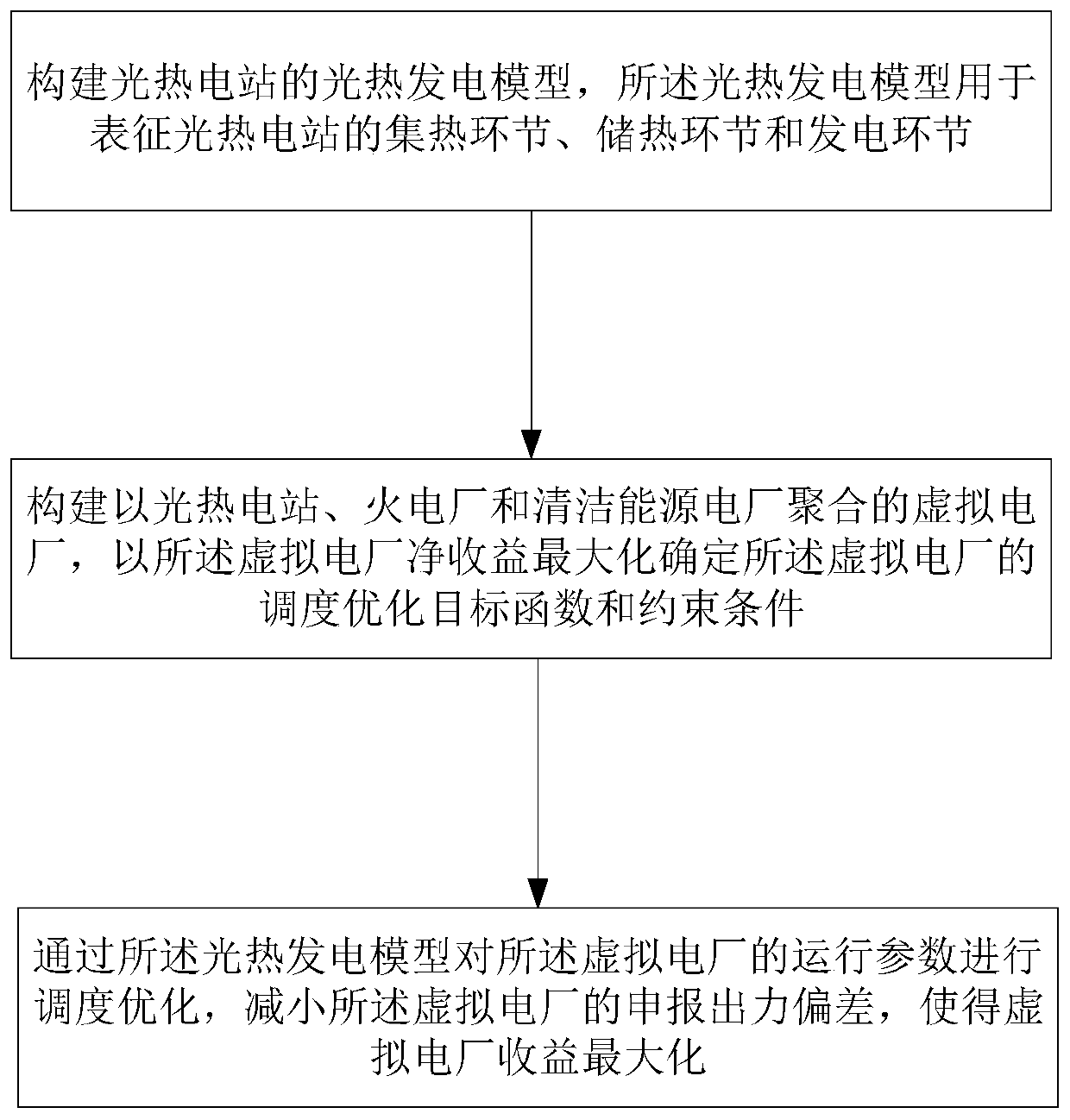
[0044] like figure 1 As shown, in this embodiment, the virtual power plant optimal scheduling method including solar thermal power plants, the steps include:

[0045] S1. Construct the photothermal power generation model of the photothermal power station, and the photothermal power generation model is used to represent the heat collection link, heat storage link and power generation link of the photothermal power station;

[0046] S2. Construct a virtual power plant aggregated by solar thermal power plants, thermal power plants and clean energy power plants, and determine the scheduling optimization objective function and constraints of the virtual power plant by maximizing the net income of the virtual power plant;

[0047] S3. Scheduling and optimizing the op...


PUM


Abstract

The invention discloses an optimal dispatching method for a virtual power plant containing a photothermal power station, which comprises the following steps: S1, constructing a photothermal power generation model of a photothermal power station, which is used to characterize the heat collection, heat storage and power generation links of the photothermal power station; S2, constructing a virtual power plant combining the photothermal power station, a thermal power plant and a clean energy power plant, and determining the objective function and constraints of dispatching optimization of the virtual power plant by maximizing the net income of the virtual power plant; and (3) optimizing the operation parameters of the virtual power plant through the photothermal power generation model so as to reduce the deviation of declared output of the virtual power plant and maximize the income of the virtual power plant. The method of the invention is simple, and can improve the adjustment flexibility of the virtual power plant, enable the virtual power plant to obtain better operation benefit, maximize the net income in the dispatching cycle, improve the energy utilization efficiency and reduceenvironmental pollution.

Description

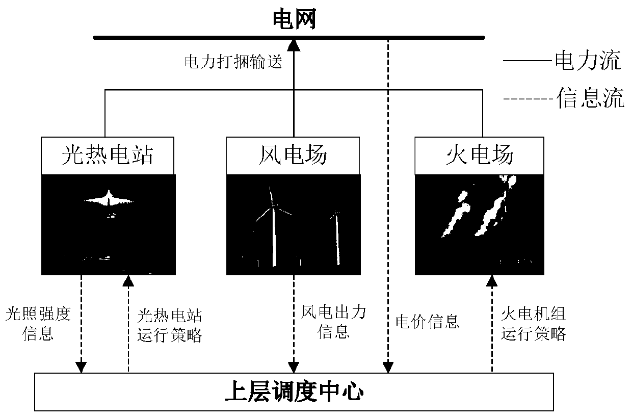
technical field [0001] The invention relates to the technical field of dispatching of power plants, in particular to an optimal dispatching method of a virtual power plant including solar thermal power stations. Background technique [0002] The rapid development of wind power technology has alleviated the energy crisis to a certain extent, but due to its strong volatility and intermittent characteristics, wind power is difficult to be directly dispatched like thermal power. The virtual power plant can aggregate various distributed resources such as wind power units, thermal power units, and controllable loads in terms of electrical characteristics, and use advanced information technology and multi-level control methods to coordinate and optimize the operation of each internal unit, and deliver them in bundles Declaring output to the power grid, so it can effectively stabilize the fluctuations caused by wind power grid connection, and realize the direct dispatch of wind powe...

Claims


Application Information

Patent Timeline
Patent Type & Authority Applications(China)
IPC IPC(8): H02J3/00H02J3/38G06Q10/06G06Q50/06
CPCH02J3/383H02J3/386H02J3/00H02J3/008G06Q10/06312G06Q50/06H02J2310/64H02J2203/20Y02E10/56Y02E10/76Y04S10/50Y02E40/70
Inventor 周任军彭院院李斌方绍凤邓子昂殷旭锋
Owner CHANGSHA UNIVERSITY OF SCIENCE AND TECHNOLOGY
Learn More