
Intelligent locating pin

A technology of intelligent positioning and pulling rods, applied in the direction of controlling mechanical energy, electrical components, electromechanical devices, etc., can solve the problems of low reliability and prone to mechanical failures, reduce maintenance costs, eliminate the possibility of being magnetized, and facilitate operation Effect

Active Publication Date: 2019-08-16
山西泰润达科技有限公司
View PDF6 Cites 0 Cited by
  • Summary
  • Abstract
  • Description
  • Claims
  • Application Information

AI Technical Summary

Problems solved by technology

[0003] The purpose of the present invention is to overcome the shortcomings of the prior art, provide an intelligent positioning pin, and solve the technical problems of easy mechanical failure and low reliability existing in the existing positioning pin control technology

Method used


Image

  • Intelligent locating pin
  • Intelligent locating pin

Examples


Embodiment Construction

[0014] The present invention will be described in further detail below in conjunction with the accompanying drawings and embodiments.

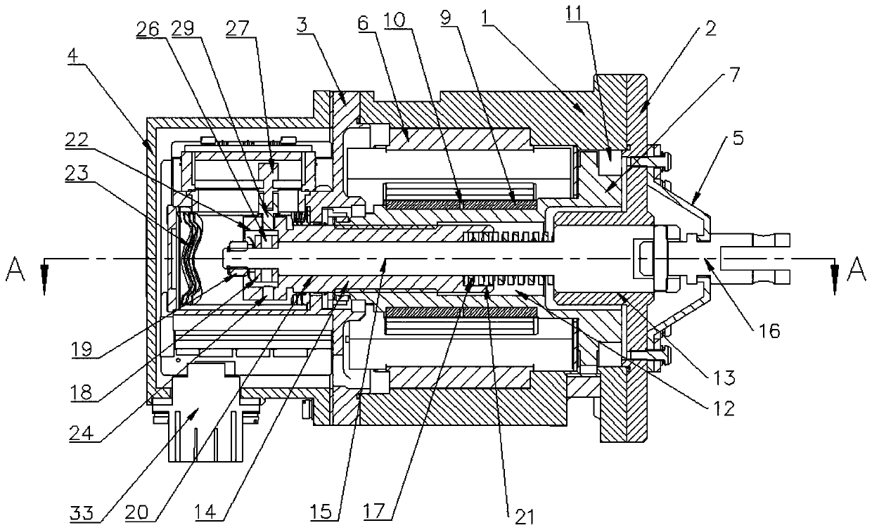
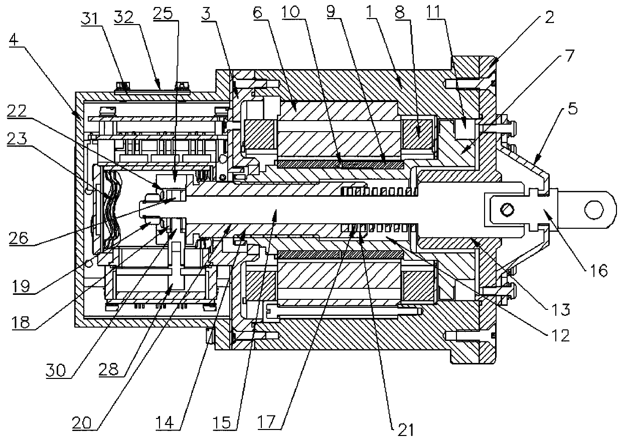
[0015] Such as figure 1 and figure 2 As shown, an intelligent positioning pin in this embodiment includes a housing, a screw rod 14 transmission, a brushless DC motor, a position sensor and a control module;

[0016] The housing includes a main housing 1, a front cover 2, an electrical bracket 3 and a rear cover 4, the front cover 2 is arranged on one side of the main housing 1, and the rear cover 4 is arranged on the other side of the main housing 1 On one side, the electrical bracket 3 is arranged in the inner cavity of the rear cover 4, and the electrical bracket 3 is fixed between the rear cover 4 and the main housing 1; the middle part of the front cover 2 is provided with a transmission hole 13, A dust cover 5 is installed on the front cover plate 2 outside the transmission device through hole 13;

[0017] The brushless DC motor is a...


PUM


Abstract

The invention relates to an intelligent locating pin, belongs to the technical field of electronic equipment control, and solves the technical problems of mechanical failure and low reliability existing in the existing locating pin control technology. The technical scheme is as follows: the intelligent locating pin comprises a housing, a lead screw drive device, a brushless DC motor, a position sensor and a control module. The housing comprises a main housing, a front cover plate, an electrical support and a rear cover. The front cover plate is arranged on one side of the main housing. The rear cover is arranged on the other side of the main housing. The electrical support is arranged in the internal cavity of the rear cover. The electrical support is fixed between the rear cover and the main housing. A drive device through hole is arranged in the middle of the front cover plate. A dust cover is arranged on the front cover plate of the outer side of the drive device through hole. The intelligent locating pin has the advantages of simple structure, convenient operation, avoiding mechanical failure and high reliability.

Description

technical field [0001] The invention belongs to the technical field of electronic equipment control, in particular to an intelligent positioning pin. Background technique [0002] The traditional way of controlling the receiving / exporting of positioning pins is controlled by electromagnets. The electromagnets are installed on the axis of the positioning pins. When the system receives the sales order, the electromagnet coil is energized and the positioning pins are attracted. Recovery; when the system receives the pin-out command, the electromagnet coil breaks, and the positioning pin is released out of the pin. This traditional method is characterized by a simple structure, but after long-term use, this method has also exposed certain shortcomings: 1. After a certain number of mechanical pull-in collisions, the electromagnet core and positioning pin are easily Deformation occurs, causing the axis and motion trajectory of the positioning pin to be out of line, causing mechan...

Claims


Application Information

Patent Timeline
Patent Type & Authority Applications(China)
IPC IPC(8): H02K7/06H02K11/21H01H3/28H02P6/08H02P6/16F16B19/02
CPCH02K7/06H02K11/21H01H3/28H02P6/08H02P6/16F16B19/02
Inventor 周勇
Owner 山西泰润达科技有限公司
Learn More