Parallel Current Sharing Control Method for Phase Wrong Full Bridge Converters of AC Power Supply Device

A technology of supply device and AC power supply, applied in the field of AC power supply device, can solve the problems of uneven parallel current, output voltage distortion, increased manufacturing cost, etc.

Active Publication Date: 2022-04-19
GOOD WILL INSTR
View PDF4 Cites 0 Cited by
  • Summary
  • Abstract
  • Description
  • Claims
  • Application Information

AI Technical Summary

Problems solved by technology

[0002] The pulse modulation circuit in a traditional AC power supply device usually receives a set of input signals and a set of triangular carrier signals from an input circuit. The input circuit includes two identical amplifying circuits, and connects two The dead zone controller is connected to two full-bridge converters to output two voltage signals at a time, but it has the problem of large output voltage distortion
[0003] In the prior art, there is another interleaved pulse modulation circuit, which also receives a set of input signals and two sets of triangular carrier signals through an input circuit, and the input circuit also includes two identical amplifying circuits. An amplifying circuit is connected with two dead-zone controllers, although the problem of distortion is reduced, but the problem of uneven current after two sets of full-bridge converters are connected in parallel
[0004] According to the prior art, the pulse modulation circuit of the AC power supply device has the problem of output voltage distortion, uneven parallel current, and increased manufacturing cost. It is still necessary to propose a more solution

Method used


Image

  • Parallel Current Sharing Control Method for Phase Wrong Full Bridge Converters of AC Power Supply Device
  • Parallel Current Sharing Control Method for Phase Wrong Full Bridge Converters of AC Power Supply Device

Examples


Embodiment Construction

[0032] In the following, the technical means adopted by the present invention to achieve the intended purpose of the invention will be further described in conjunction with the accompanying drawings and preferred embodiments of the present invention.

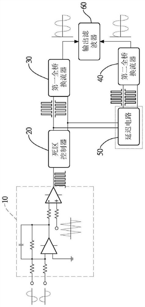
[0033] For preferred embodiments of the present invention, please refer to figure 1 As shown, it includes an input circuit 10, a dead zone controller 20, a first full bridge converter 30, a second full bridge converter 40, a delay circuit 50 and an output filter 60; wherein, the The input circuit 10 has more than one signal input terminal and a signal output terminal, and the signal input terminal of the input circuit 10 is used to receive a sinusoidal reference signal and a feedback signal, and generate a control signal according to a triangular carrier signal; in this comparison In a preferred embodiment, the input circuit includes a feedback control circuit; the dead zone controller 20 includes more than one inverter.

[003...


PUM


Abstract

The invention discloses a method for controlling parallel current sharing of phase-staggered full-bridge converters of an AC power supply device, which includes a feedback control circuit, a dead zone controller, a first full-bridge converter, and a second full-bridge A converter and a delay circuit, the output terminal of the dead zone controller is electrically connected to the input terminal of the first full bridge converter, the input terminal of the delay circuit is connected to the dead zone controller, the first full bridge converter Between the converters, the output end of the delay circuit is electrically connected to the input end of the second full-bridge converter, and the delay circuit receives a set of pulse width modulation signals, when the delay circuit receives the set of pulse width modulation signals Then, according to a time delay control process, the group of pulse width modulation signals is adjusted to generate another group of pulse width modulation signals, so that the output voltages of the first full-bridge converter and the second full-bridge converter The phases are staggered by 180 degrees and consistent, so as to achieve the purpose of reducing manufacturing costs and achieving the effect of current sharing after parallel connection.

Description

technical field [0001] The invention relates to an AC power supply device, in particular to a parallel current sharing control method for a phase-staggered full-bridge converter of the AC power supply device. Background technique [0002] The pulse modulation circuit in a traditional AC power supply device usually receives a set of input signals and a set of triangular carrier signals from an input circuit. The input circuit includes two identical amplifying circuits, and connects two Only when the dead zone controller is connected with two full-bridge converters can it output two voltage signals at one time, but it has the problem of large output voltage distortion. [0003] In the prior art, there is another interleaved pulse modulation circuit, which also receives a set of input signals and two sets of triangular carrier signals through an input circuit, and the input circuit also includes two identical amplifying circuits. An amplifying circuit is connected to two dead-...

Claims


Application Information

Patent Timeline
Patent Type & Authority Patents(China)
IPC IPC(8): H02M1/088
CPCH02M1/088
Inventor 林凯民
Owner GOOD WILL INSTR
Why Eureka
Try Eureka