
Portable radar signal modulator based on phase modulation surface

A portable radar and phase modulation technology, applied in instruments, supporting machines, reflection/re-radiation of radio waves, etc., can solve problems such as differences in actual product performance, no public reports on experimental modulators, etc., to achieve simple product structure, overall The structure is flexible and portable, and the cost is low.

Pending Publication Date: 2019-08-20
NAT UNIV OF DEFENSE TECH
View PDF0 Cites 1 Cited by
  • Summary
  • Abstract
  • Description
  • Claims
  • Application Information

AI Technical Summary

Problems solved by technology

[0003] The application feasibility and performance reliability of the phase modulation surface in the field of signal modulation have been fully proved, but because the manufacturing process of the phase modulation surface will affect its own performance to a certain extent, it often leads to theoretical analysis results and actual products. There are certain differences in performance, so the experimental verification of the performance of the phase modulation surface is particularly critical
Under this practical demand, the present invention designs a portable general-purpose radar signal modulator based on a phase modulation surface. The modulator takes the phase modulation surface as the main body and uses a tripod-like structure as the support body. At present, there is no relevant experimental modulator. see public report

Method used


Image

  • Portable radar signal modulator based on phase modulation surface
  • Portable radar signal modulator based on phase modulation surface
  • Portable radar signal modulator based on phase modulation surface

Examples


Embodiment Construction

[0049] The technical solutions of the present invention will be further described below in conjunction with the accompanying drawings and specific embodiments. A portable radar signal modulator based on a phase modulation surface, including a signal modulation body and a carrying platform body:

[0050] (1) Signal Modulator Body: Phase Modulation Surface

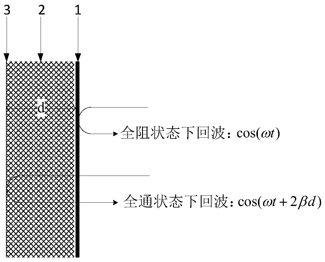
[0051] The phase modulation surface is designed as a three-layer structure, which is an active impedance layer 1, a foam medium 2 and a conductor backplane 3 from top to bottom, and its specific implementation is as follows.

[0052] Active impedance layer 1 adopts a "bow tie" metal unit, and loads a BA585 PIN diode between two adjacent units, and changes the current passing through the diode by applying a bias voltage to the entire structure; the unit structure size is shown in the attached Figure 3a As shown, the overall structure size is 30cm×30cm, according to the size of the bow tie metal unit structure (made of coppe...


PUM


Abstract

The invention discloses a portable radar signal modulator based on a phase modulation surface. The modulator comprises a signal modulator main body which is a phase modulation surface, and a carryingplatform main body which is a tripod-like structure. The phase modulation surface is composed of an active impedance layer, a conductor back plate and a foam medium. The active impedance layer adopts"bow tie type" metal units, and a BA585 type PIN diode is loaded between two adjacent units. The foam medium is located between the active impedance layer and the conductor back plate. The conductor back plate is made of a metal sheet capable of totally reflecting an electromagnetic wave. The tripod-like structure consists of a triangular support frame, a rotating shaft and a rotating telescopic clamp. The modulator can adapt to different frequency bands of an electromagnetic wave signal, can realize carrying of a phase modulation surface product, and can adapt to a dimensional change; pitching and azimuth omnibearing rotation can be achieved, and height adjustment is flexible and controllable; the modulator does not react strongly to an incident electromagnetic wave; an overall structureis flexible and portable; a product structure is simple; and electromagnetic wave active radiation can be avoided and a detected probability is reduced.

Description

technical field [0001] The invention relates to a portable radar signal modulator based on a phase modulation surface, which has the characteristics of compactness, portability, and flexible performance. The portable radar signal modulator belongs to the field of radar signal modulation devices. Background technique [0002] As a special frequency selective surface structure that can change the reflection characteristics of electromagnetic waves, the phase modulation surface can dynamically control the characteristics of its body reflecting electromagnetic echoes. It redistributes the incident wave energy in a larger frequency range by applying phase modulation to the incident electromagnetic wave signal, which can not only achieve target stealth, but also produce realistic targets within the radar bandwidth. Researchers have carried out a lot of preliminary theoretical research , and is gradually carrying out the development and test verification of phase modulation surface...

Claims


Application Information

Patent Timeline
Patent Type & Authority Applications(China)
IPC IPC(8): G01S13/28G01S7/02G01S7/28F16M11/28F16M11/08F16M11/10
CPCG01S13/288G01S7/02G01S7/28F16M11/28F16M11/08F16M11/10
Inventor 冯德军张然王俊杰艾小锋刘蕾
Owner NAT UNIV OF DEFENSE TECH
Learn More