Motor stator machining device

A technology for processing devices and motor stators, applied in electric processing equipment, accessory devices, metal processing equipment, etc., can solve the problems of low pass rate of finished workpieces, low degree of material processing automation, and inability to realize flexible processing, etc., to improve processing efficiency effect

Inactive Publication Date: 2021-05-04
安徽广博机电制造股份有限公司
View PDF11 Cites 0 Cited by
  • Summary
  • Abstract
  • Description
  • Claims
  • Application Information

AI Technical Summary

Problems solved by technology

[0006] The technical solutions disclosed in the patents disclosed in the above prior art can only single-position the stator workpiece for processing, and the stator workpiece often has multiple processing procedures during the processing process. Obviously, the technical solutions disclosed in the above patent documents cannot realize flexible processing. Multi-channel processing sections realize synergistic cooperation, integrated processing, and improve processing efficiency
[0007] Based on the device defects disclosed in the prior art, the degree of automation of material processing is low, the processing efficiency is not high, and it relies too much on human intervention, resulting in a low pass rate of finished workpieces.

Method used


Image

  • Motor stator machining device
  • Motor stator machining device
  • Motor stator machining device

Examples


Embodiment 1

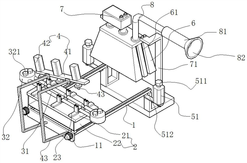
[0068] Such as figure 1 As shown, a motor stator processing device includes sliding frame rods 1 arranged at intervals on the left and right; the sliding frame rod 1 is a rod-shaped frame and a stainless steel frame.

[0069] A feeding assembly 2 is slidably connected between the carriage rods 1 . The material (motor stator workpiece, workpiece including the motor shaft and the winding assembled on the motor shaft), the feeding limit is on the feeding assembly 2, and the automatic lifting and rotating materials are realized through the feeding assembly 2, which is convenient for flexible angle and height switching of materials.

[0070] Specifically, each feeding assembly 2 includes a rectangular material seat plate 21 (the size of the material seat plate 21 is 1.2n in length and 90 cm in width, made of stainless steel plate).

[0071] In order to realize that several material workpieces are carried to limit positions, several material racks arranged at intervals from left to...

Embodiment 2

[0085] Such as Figure 1-6 As shown, in order to realize the forward movement of the feeding assembly 2 and facilitate the entry into the second process for processing, the above feeding assembly 2 also includes a screw driving part 9 that drives the material seat plate 21 to move.

[0086] Specifically, the screw driving part 9 includes four seat blocks 931 fixedly connected to the bottom of the material seat plate 21 , and the seat blocks 931 are respectively located at four corners of the material seat plate 21 . The top of the seat block 931 is mounted on the top surface of the sliding frame rod 1 , specifically, the sliding frame rod 1 is provided with a chute 12 , and the seat block 931 is slidably mounted on the notch of the chute 12 .

[0087] A sliding sphere 93 is fixedly connected to the bottom of each block 931 , and the screw driving part 9 further includes a screw 92 threaded on the sliding sphere 93 .

[0088] Such as figure 1 As shown, the rear end of the lea...

Embodiment 3

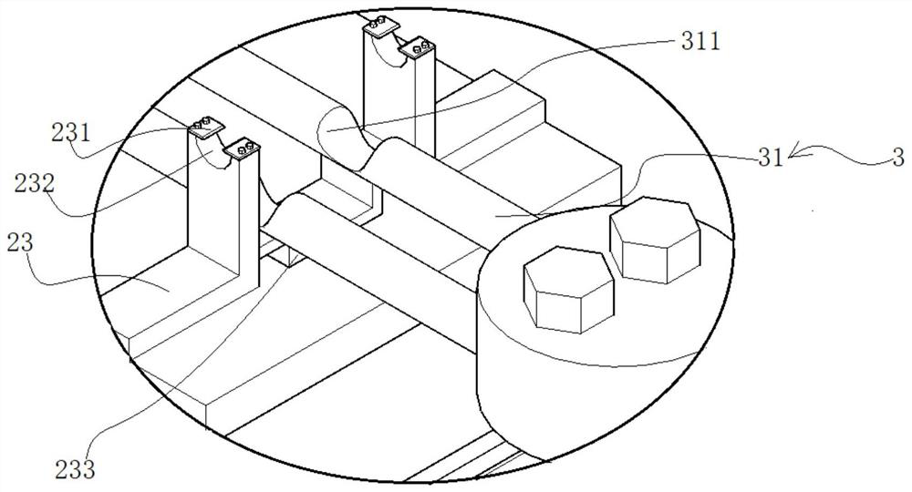
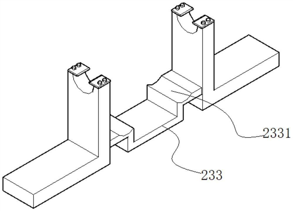
[0094] Such as Figure 1-9 As shown, after the material is processed on the material seat plate 21, it needs to be processed in the next stage of processing. In order to realize the simultaneous removal of the material from the material seat plate 21, there is a ejector rod assembly between the above-mentioned folded connecting plates 233. 3. The ejector rod assembly 3 realizes the simultaneous removal of materials.

[0095] Specifically, the ejector rod assembly 3 includes two ejector rods 32 arranged at intervals between the front and the rear, and the tops of the ejector rods 32 are provided with a plurality of lap notches 311 arranged at intervals from left to right. 311 is located between the racks; end seats 32 are installed between the left and right ends of the ejector rod 32 .

[0096] Specifically, a socket that cooperates with the ejector rod 32 is provided on the end seat 32, and the end of the ejector rod 32 is inserted in the socket. The positioning bolt 321 is...


PUM


Abstract

The invention discloses a motor stator machining device. The motor stator machining device comprises sliding frame rods which are arranged in a left-right spaced mode. A feeding component is connected between the sliding frame rods in a sliding mode and used for feeding, the feeding component further comprises a power part for driving a material carrying frame to ascend, descend and rotate, the angle and the height of a machining site are adjusted, and the motor stator machining device further comprises an ejector rod component; the ejector rod component is used for simultaneously stripping machined material workpieces and feeding the machined material workpieces to the next workshop section equipment, and the feeding component further comprises a lead screw driving part for driving a material seat plate to move; the lead screw driving part is used for driving the feeding component to move for discharging; and the motor stator machining device further comprises an electric spark machining part matched with a driving jacking part, and the electric spark machining part conducts electric spark machining on materials. According to the motor stator machining device disclosed by the invention, the integration of feeding, stripping and feeding is realized, a plurality of pieces of machining procedure equipment are organically combined, and the machining and production efficiency of a motor stator is effectively improved.

Description

technical field [0001] The invention relates to the field of motor processing devices, in particular to a motor stator processing device. Background technique [0002] Motor stators are an important part of motors such as generators and starters. The stator is an important part of the motor. The stator is composed of three parts: stator core, stator winding and frame. In the motor machining process, it is necessary to process the stator parts of the motor, such as through electric discharge machining, to process the targeted motor electrodes. [0003] In the process of processing, the existing technology adopts simple tooling and fixtures to position the processing materials, and then carries out loading and feeding. In the processing process, it is necessary to continuously switch the angle of the processing materials to facilitate the processing of working equipment. Obviously, the processing methods disclosed in the prior art Does not have the above-mentioned functiona...

Claims


Application Information

Patent Timeline
Patent Type & Authority Applications(China)
IPC IPC(8): B23H1/00B23H11/00
CPCB23H1/00B23H11/00B23H11/003
Inventor 何炎陈岳峰罗永明冯杜龙刘新成
Owner 安徽广博机电制造股份有限公司
Why Eureka
Try Eureka