
Manufacturing method for micro holes of additive manufacturing part

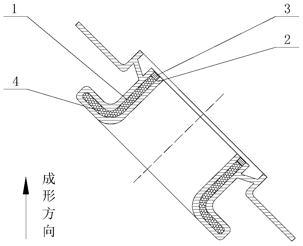
An additive manufacturing and manufacturing method technology, applied in the field of laser selective melting additive manufacturing, can solve the problems of difficult filling and removal of protective materials, poor surface roughness of holes, and easy damage to the wall of the cavity, saving processes, The effect of good sealing, avoiding damage and contamination

Active Publication Date: 2019-08-23
AECC AVIATION POWER CO LTD
View PDF5 Cites 3 Cited by
  • Summary
  • Abstract
  • Description
  • Claims
  • Application Information

AI Technical Summary

Problems solved by technology

[0002] At present, typical parts such as aero-engine swirlers, nozzle casings, and turbine blades all have complex cavity structures. It is difficult to ensure that the small holes are less than The precision of tiny holes is high, and it is easy to be blocked by powder, and the surface roughness of the holes is poor
[0003] For additively manufactured parts with high requirements for micro-hole wall roughness and dimensional accuracy, micro-holes are generally processed by EDM, laser and other methods, but this method is easy to damage the opposite wall of the cavity when the micro-hole penetrates. Using special methods for protection or control, filling protective materials is a common solution, but for additive manufacturing parts with complex cavity structures, the filling and removal of protective materials are relatively difficult

Method used


Image

  • Manufacturing method for micro holes of additive manufacturing part
  • Manufacturing method for micro holes of additive manufacturing part
  • Manufacturing method for micro holes of additive manufacturing part

Examples


Embodiment Construction

[0035] In order to make the purpose, technical solutions and advantages of the embodiments of the present invention clearer, the technical solutions of the present invention will be clearly and completely described below in conjunction with the accompanying drawings. Obviously, the described embodiments are part of the embodiments of the present invention, not all of them. the embodiment. Based on the embodiments of the present invention, all other embodiments obtained by persons of ordinary skill in the art without making creative efforts belong to the protection scope of the present invention.

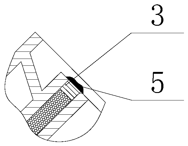
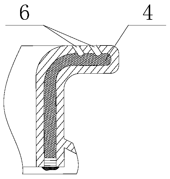
[0036] The invention proposes a cavity structure in which the metal powder in the cavity is not removed immediately after the part laser selective melting forming process is completed, and the cavity structure of the part is closed and sealed, and then the micro hole is processed by the method of electric spark and laser. After the micro hole processing is completed, use an explosion...


PUM


Abstract

The invention discloses a manufacturing method for micro holes of an additive manufacturing part. The manufacturing method comprises the following steps: step I, sealing an outlet end of a cavity structure with support while forming a part with the cavity structure through laser selective melting and additive manufacturing, and enabling the outlet end of the cavity structure to face towards a forming direction, thereby obtaining the part with the cavity structure; step II, drying the obtained part; step III, completely sealing the outlet end of the dried part with a sealing material; step IV,performing micro hole processing on the completely sealed part; step V, removing the sealing material and the support after micro hole processing is accomplished; and step VI, clearing powder in the cavity structure. The laser selective melting and additive manufacturing technical feature is adopted to take powder in a forming process as a cavity protective material to perform micro hole processing, so that a follow-up special material filling process is saved, and powder in the cavity is filled more compact, and therefore, damages and pollution on the inner wall of the cavity in a micro holeprocessing process can be affectively avoided.

Description

technical field [0001] The invention belongs to the technical field of laser selective melting and additive manufacturing, and in particular relates to a method for manufacturing tiny holes in additive manufactured parts. Background technique [0002] At present, typical parts such as aero-engine swirlers, nozzle casings, and turbine blades all have complex cavity structures. It is difficult to ensure that the small holes are less than The precision of tiny holes is high, and it is easy to be blocked by powder, and the surface roughness of the holes is poor. [0003] For additively manufactured parts with high requirements for micro-hole wall roughness and dimensional accuracy, micro-holes are generally processed by EDM, laser and other methods, but this method is easy to damage the opposite wall of the cavity when the micro-hole penetrates. Using special methods for protection or control, filling protective materials is a common solution, but for additive manufacturing ...

Claims


Application Information

Patent Timeline
Patent Type & Authority Applications(China)
IPC IPC(8): B22F3/105B22F3/24B33Y10/00
CPCB22F3/24B33Y10/00B22F2003/247B22F10/00B22F10/66B22F10/28B22F10/47B22F10/68Y02P10/25
Inventor 谢国印胡思嘉陈娟娟曹志勇闫文彭颖周峰仇荣俊
Owner AECC AVIATION POWER CO LTD
Learn More