

Solar blind ultraviolet imaging background light suppression optical system and method
An ultraviolet imaging and optical system technology, which is applied in the field of weak optical signal detection, can solve the problems of long detection distance, high requirements for detector sensitivity and narrow-band transmittance of optical filter, weak discharge signal, etc., and achieves low background interference , The design of the instrument is reasonable, the effect of clear imaging
- Summary
- Abstract
- Description
- Claims
- Application Information
AI Technical Summary
Problems solved by technology
Method used
Image


Examples
Embodiment 1
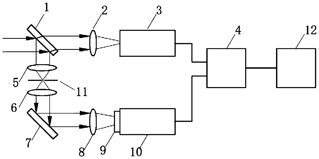
[0020] Such as figure 1 As shown, a solar-blind ultraviolet imaging background light suppression optical system, the incident light is divided into the visible light imaging optical path and the ultraviolet light imaging optical path after being obliquely placed all-reflection full lens A1; the visible light imaging optical path is set in sequence: visible light imaging objective lens 2 , Visible light CCD3; UV light imaging light path is set in turn: filter lens group, total reflection full lens B7, ultraviolet imaging objective lens 8, solar blind filter 9, ultraviolet solar blind CCD10; visible light CCD and ultraviolet solar blind CCD transmit images to the image processing system 4; through the image processing system, the visible light image and the ultraviolet signal light are filtered and fused, and the image is displayed on the display screen 12 after being fused by the image processor 4; the filter lens group is sequentially filtered along the light propagation direct...
Embodiment 2
[0025] An optical method for suppressing background light in solar-blind ultraviolet imaging, in which incident light is divided into a visible light imaging optical path and an ultraviolet light imaging optical path after being obliquely placed with a total reflection full lens A; wherein the visible light imaging optical path is sequentially set as: a visible light imaging objective lens and a visible light CCD; The ultraviolet light imaging optical path is set in sequence: total reflection full lens B, ultraviolet imaging objective lens, ultraviolet solar blind CCD; visible light CCD, ultraviolet solar blind CCD transmits the image to the image processing system; the incident light passes through the total reflection full lens A placed obliquely After the visible light is transmitted, the visible light imaging optical path is set on this transmission optical path, and the visible light is imaged on the visible light CCD after passing through the visible light imaging objectiv...
PUM
 Abstract
Description
Claims
Application Information