
Continuous zooming ultrasonic probe and zooming method adopted by same

A technology of ultrasonic probe and ultrasonic transducer, applied in ultrasonic/sonic/infrasonic diagnosis, ultrasonic/sonic/infrasonic Permian technology, ultrasonic/sonic/infrasonic image/data processing, etc. Micro-imaging system resolution and detection sensitivity, difficulty in obtaining lateral resolution and depth resolution, and difficulty in signal-to-noise ratio of non-zoom ultrasound probes, etc., to achieve the effects of promoting and applying, improving detection sensitivity, uniform image resolution and contrast

Active Publication Date: 2016-10-26
SOUTH CHINA NORMAL UNIVERSITY
View PDF5 Cites 7 Cited by
  • Summary
  • Abstract
  • Description
  • Claims
  • Application Information

AI Technical Summary

Problems solved by technology

[0004] At present, the ultrasonic probe used in photoacoustic microscopic imaging technology is difficult to achieve acoustic continuous zoom, difficult to obtain higher lateral resolution and depth resolution, and cannot achieve multi-level imaging in the depth direction; in photoacoustic microscopic imaging Most of the ultrasonic probes used in the technology are non-annular ultrasonic probes, it is difficult to ensure that the incident light is coaxial with the ultrasonic probe, which will eventually affect the resolution and detection sensitivity of the photoacoustic microscopy imaging system; more particularly, for photoacoustic microscopy The speckle light source in the technology, the non-zoom ultrasound probe is difficult to obtain a higher signal-to-noise ratio, and the detection sensitivity is not high

Method used


Image

  • Continuous zooming ultrasonic probe and zooming method adopted by same
  • Continuous zooming ultrasonic probe and zooming method adopted by same
  • Continuous zooming ultrasonic probe and zooming method adopted by same

Examples


Embodiment 1

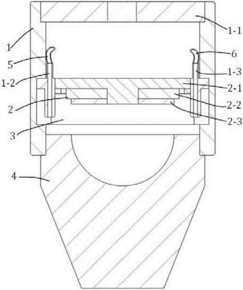
[0038] to combine figure 1 , figure 2 and Figure 10As shown, the annular ultrasonic transducer 2 includes a convex optical lens 2-1, an annular sound-absorbing plate 2-2, and an annular piezoelectric element 2-3, wherein the piezoelectric material of the annular piezoelectric element 2-3 is PVDF piezoelectric Electrode film with a thickness of 9 μm, adopts a ring structure with an outer diameter of 8 mm and an inner diameter of 3 mm, with a main frequency of 50 MHz, a bandwidth of 80%, and a sensitivity of -55 dB. The material of convex optical lens 2-1 adopts optical glass lens material, and convex optical lens is provided with boss, and the diameter of boss is 3mm, and light transmittance is excellent, and light transmittance is more than or equal to 98%. The light transmittance of the shaped optical lens is 98%. The material of the ring-shaped sound-absorbing panel 2-2 is glass fiber material, and its thickness ranges from 1 to 5mm (this embodiment uses 4mm), an outer ...

Embodiment 2

[0046] Using a photoacoustic microscope ultrasound probe in Example 1, its performance of transmitting and receiving signals was tested.

[0047] Olympus 5073PR ultrasonic transmitter receiver is used as the trigger signal source, its emission intensity is 12.5μJ, pulse repetition frequency is 5KHz; Taylor oscilloscope TDS2012B is used as the echo signal receiving; steel material plate is used as the test block, the thickness is 10MM, and the sound velocity is 5320m / s.

[0048] First connect the Olympus 5073PR ultrasonic transmitter receiver, Taylor oscilloscope TDS2012B, and the ultrasonic probe in Example 1, and place the Olympus 5073PR ultrasonic transmitter receiver in the transmitting and receiving state; secondly, apply an appropriate amount of couplant, use a syringe to inject the glycerin-ethanol mixture into the cavity 3 of the ultrasonic probe from the liquid inlet pipe 5 of the ultrasonic probe in Example 1 until the cavity 3 is filled, and there are no air bubbles ...


PUM

PropertyMeasurementUnit
Densityaaaaaaaaaa
Diameteraaaaaaaaaa
Thicknessaaaaaaaaaa

Abstract

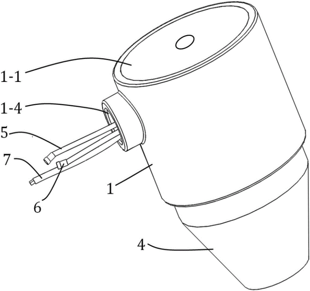
The invention provides a continuous zooming ultrasonic probe. The continuous zooming ultrasonic probe comprises a shell, an annular ultrasonic transducer and a continuous zooming acoustic lens, wherein the annular ultrasonic transducer is arranged on the inner wall of the shell, and is provided with an emitting / receiving surface for emitting / receiving ultrasonic waves; the continuous zooming acoustic lens comprises a first lens part with acoustic impedance capable of changing continuously and a second lens part provided with a hemispherical groove; and the annular ultrasonic transducer, the inner wall of the shell and the second lens part define a sealed accommodating cavity. The invention further relates to a continuous zooming method. According to the continuous zooming ultrasonic probe and the continuous zooming method, the special acoustic lens capable of realizing continuous zooming is adopted, therefore, the multi-level depth imaging can be realized, the aberration of the special acoustic lens is corrected till reaching the degree of high-resolution imaging having transverse resolution and depth resolution, and the continuous zooming ultrasonic probe and the continuous zooming method belong to the field of nondestructive testing.

Description

technical field [0001] The invention belongs to the field of non-destructive testing, and more particularly, the invention is applicable to the field of photoacoustic microscopic imaging, and relates to a continuous zoom ultrasonic probe and a photoacoustic imaging method thereof. Background technique [0002] Ultrasound diagnosis is a diagnostic method that applies ultrasonic detection technology to the human body, and understands the data and morphology of physiological or tissue structures by measuring, discovering diseases, and making prompts. Ultrasound diagnosis is a non-invasive, painless, convenient and intuitive means of effective examination, but its imaging method depends on the acoustic impedance of biological tissue, because there is no obvious difference in the acoustic impedance of some tumor tissues, which limits the application of ultrasonic imaging technology. Scope is used and its reconstructed image has very low contrast. [0003] Photoacoustic imaging t...

Claims


Application Information

Patent Timeline
IPC IPC(8): A61B5/00A61B8/00A61B8/08
CPCA61B5/0059A61B8/085A61B8/4272A61B8/4281A61B8/4444A61B8/4483A61B8/5261
Inventor 杨思华马海钢邢达
Owner SOUTH CHINA NORMAL UNIVERSITY
Learn More