
Power battery pack and electric vehicle

A technology for power battery packs and electric vehicles, applied in the field of electric vehicles, can solve the problems of reducing the utilization rate of the inner space of the pack body 200″, the adverse effects of the quality of the power battery packs, and the stability of the power battery packs, etc., so as to improve the battery life. , the effect of increasing space utilization and expanding battery space

Active Publication Date: 2019-08-23
BYD CO LTD
View PDF12 Cites 20 Cited by
  • Summary
  • Abstract
  • Description
  • Claims
  • Application Information

AI Technical Summary

Problems solved by technology

[0006] As the user's requirements for the battery life of electric vehicles gradually increase, and in the case of limited space at the bottom of the vehicle body, the power battery pack 10' provided by the above-mentioned prior art embodiment is adopted, and the end plate of the battery module 400' used in it is , side panels, and the internal connection and installation methods of the power battery pack 10', etc., all reduce the utilization rate of the internal space of the pack body 200''; 'The volume ratio is too low, and its energy density cannot meet the needs of users for the battery life of electric vehicles, which has gradually become an important factor restricting the development of electric vehicles
In addition, there is a cumbersome assembly process, and the assembly process is complicated. It needs to be assembled into a battery module first, and then the battery module is installed in the package, which increases the cost of manpower and material resources. During the assembly process, the probability of defective rate is increased. Multiple assembly increases the possibility of loosening and insecure installation of the power battery pack, which will have a negative impact on the quality of the power battery pack, and the stability of the power battery pack will decrease. , the reliability decreases

Method used


Image

  • Power battery pack and electric vehicle
  • Power battery pack and electric vehicle
  • Power battery pack and electric vehicle

Examples


Embodiment 1

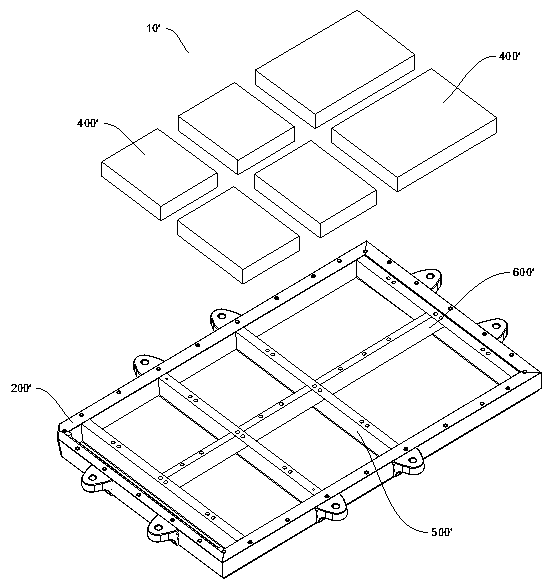
[0194] According to the power battery pack 10 of the embodiment of the present application, such as Figure 12 As shown, the length direction of the single battery 100 is arranged along the width direction B of the power battery pack, and a plurality of single cells 100 are arranged along the length direction A of the power battery pack 10. In the width direction B of the power battery pack, the package body 200 Two single cells 100 are accommodated. A width direction beam 500 and a length direction beam 600 are arranged inside the package body 200 , the width direction beam 500 extends along the width direction B of the power battery pack 10 , and a plurality of single cells 100 are arranged along the length direction A of the power battery pack 10 to form Battery array, width direction beam 500 divides the battery array into two parts along the length direction A of the power battery pack 10 . In addition, the plurality of single batteries 100 are arranged in two rows of ba...

Embodiment 2

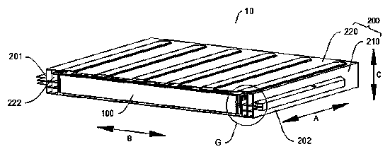
[0196] According to the power battery pack 10 of the embodiment of the present application, such as Figure 13 As shown, the length direction of the single battery 100 is arranged along the width direction B of the power battery pack, and a plurality of single cells 100 are arranged along the length direction A of the power battery pack 10. In the width direction B of the power battery pack, the package body 200 A single battery 100 is accommodated, and the single battery 100 extends from one side of the package body 200 to the other side in the width direction B of the power battery pack 10 . A transverse beam 500 in the width direction is arranged inside the package body 200, and the transverse beam 600 in the longitudinal direction is not provided. The transverse beam 500 in the width direction extends along the width direction B of the power battery pack 10, and a plurality of single cells 100 are arranged along the length direction A of the power battery pack 10. A batter...

Embodiment 3

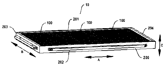
[0198] According to the power battery pack 10 of the embodiment of the present application, such as Figure 14 As shown, the length direction of the single battery 100 is arranged along the width direction B of the power battery pack, and a plurality of single cells 100 are arranged along the length direction A of the power battery pack 10. In the width direction B of the power battery pack, the package body 200 A single battery 100 is accommodated, and the single battery 100 extends from one side of the package body 200 to the other side in the width direction B of the power battery pack 10 . The transverse beam 500 in the width direction and the transverse beam 600 in the longitudinal direction are not provided in the enclosure 200 . The first beam 201 and the second beam 202 of the package body 200 located on both sides of the power battery pack 10 in the width direction B provide support for the single battery 100 , and the third beams of the package body 200 located at bo...


PUM

PropertyMeasurementUnit
Lengthaaaaaaaaaa

Abstract

The invention discloses a power battery pack and an electric vehicle. The power battery pack comprises a pack body and a plurality of single batteries, wherein an accommodating space is defined in thepack body, the pack body is internally provided with at least one width direction cross beam or length direction cross beam, the width direction cross beam extends in the width direction of the powerbattery pack, and the length direction cross beam extends in the length direction of the power battery pack; the accommodating space is divided into a plurality of accommodating chambers by the widthdirection cross beam or length direction cross beam; and the plurality of single batteries are set in the pack body and directly arranged in the accommodating chambers, and each accommodating chamberis internally provided with at least one single battery so as to form a battery array. The power battery pack disclosed by the embodiment of the invention has the advantages of high space utilizationrate, high energy density, strong endurance, high reliability, low cost, high quality and the like.

Description

technical field [0001] The present application relates to the technical field of batteries, in particular, to a power battery pack and an electric vehicle with the power battery pack. Background technique [0002] In the related art, such as a power battery pack applied to an electric vehicle, it mainly includes a package body and a plurality of battery modules installed in the package body, wherein each battery module group is assembled from a plurality of single cells. [0003] In the above related prior art, such as figure 1 As shown, the package body 200'' of the power battery pack 10' is mostly divided into the installation area of ​​a plurality of battery modules 400' by the width direction beam 500' and the length direction beam 600'; the battery module in the battery pack disclosed in CN107925028A The group 400' is fixed to the transverse beam 500' in the width direction or the transverse beam 600' in the longitudinal direction by means of screws or the like. The b...

Claims


Application Information

Patent Timeline
IPC IPC(8): H01M2/10H01M10/613H01M10/625H01M10/6554H01M10/6556H01M10/6568B60L50/64
CPCH01M10/613H01M10/625H01M10/6554H01M10/6556H01M10/6568B60K1/04B60K2001/0438H01M50/249H01M2220/20H01M50/131H01M50/209H01M50/103H01M50/367H01M10/6567H01M10/6569H01M50/119Y02E60/10H01M50/233H01M50/224H01M50/251H01M50/383B60K2001/0405B60L50/64B60L50/66H01M50/244H01M50/531H01M50/3425H01M50/35H01M50/342H01M50/317H01M10/052H01M10/647H01M10/6551B60L58/26H01M50/543H01M50/271H01M10/425H01M2010/4271
Inventor 孙华军朱燕唐江龙易宁郭舒
Owner BYD CO LTD
Features
  • Generate Ideas
  • Intellectual Property
  • Life Sciences
  • Materials
  • Tech Scout
  • Unparalleled Data Quality
  • Higher Quality Content
  • 60% Fewer Hallucinations
Learn More