Liquid antenna assembly and electronic equipment thereof

A technology for antenna components and electronic equipment, which is applied to antenna parts, antennas, antenna supports/mounting devices, etc., can solve the problems of traditional antenna insertion loss, excessive mobile phone clearance size, etc., to improve performance and reduce additional insertion damage effect

Inactive Publication Date: 2019-08-23
OPPO CHONGQING INTELLIGENT TECH CO LTD
View PDF6 Cites 4 Cited by
  • Summary
  • Abstract
  • Description
  • Claims
  • Application Information

AI Technical Summary

Problems solved by technology

[0003] The embodiment of the present application provides a liquid antenna assembly and its electronic equipment, which are used to solve the problem that the traditional antenna requires too much internal clearance of the mobile phone, and the traditional antenna has the problem of insertion loss

Method used


Image

  • Liquid antenna assembly and electronic equipment thereof
  • Liquid antenna assembly and electronic equipment thereof
  • Liquid antenna assembly and electronic equipment thereof

Examples


Embodiment Construction

[0011] In order to make the purpose, features and advantages of the present application more obvious and understandable, the technical solutions in the embodiments of the present application will be clearly and completely described below in conjunction with the drawings in the embodiments of the present application. Obviously, the described The embodiments are only some of the embodiments of the present application, but not all of them. Based on the embodiments in this application, all other embodiments obtained by those skilled in the art without making creative efforts belong to the scope of protection of this application.

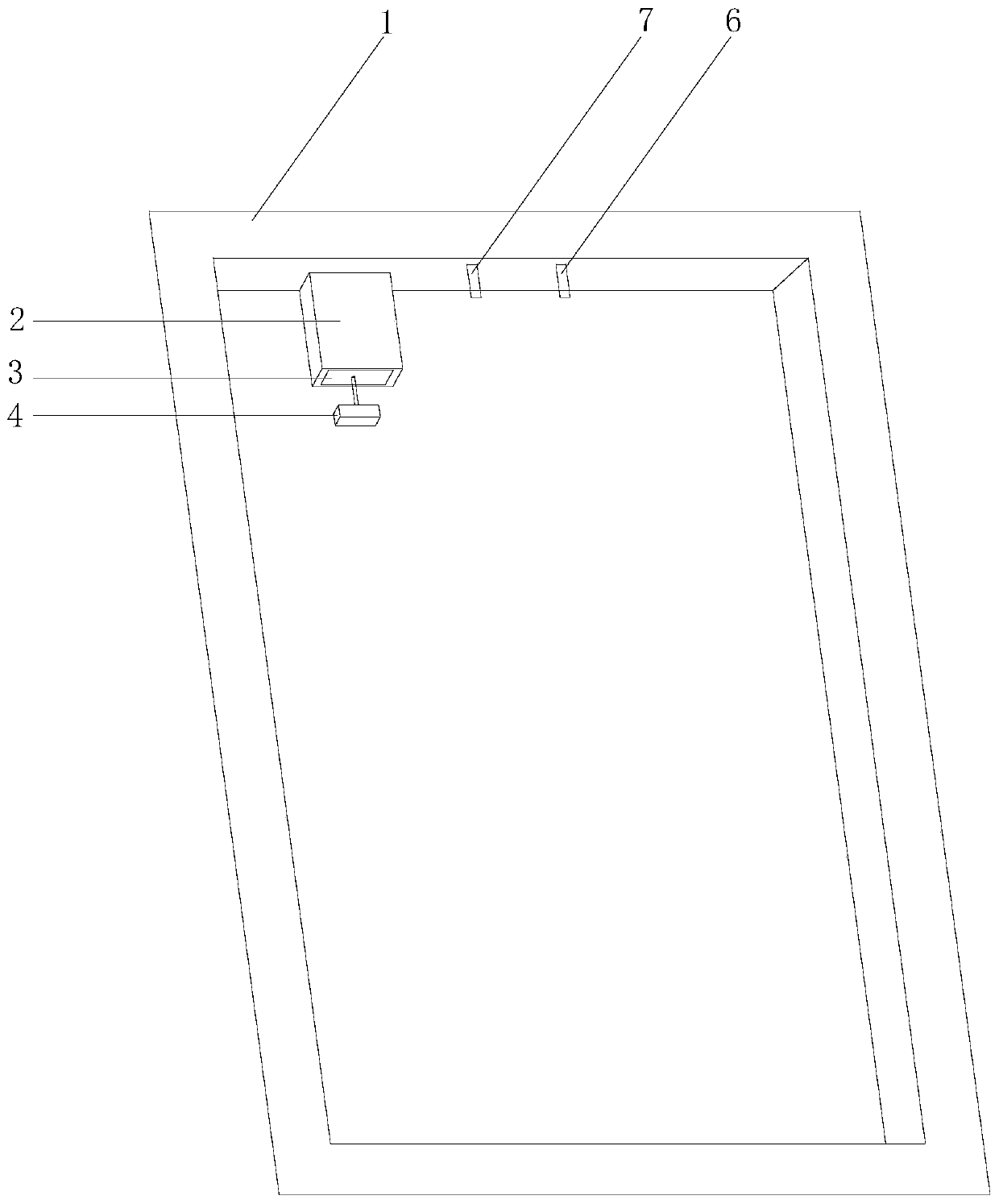
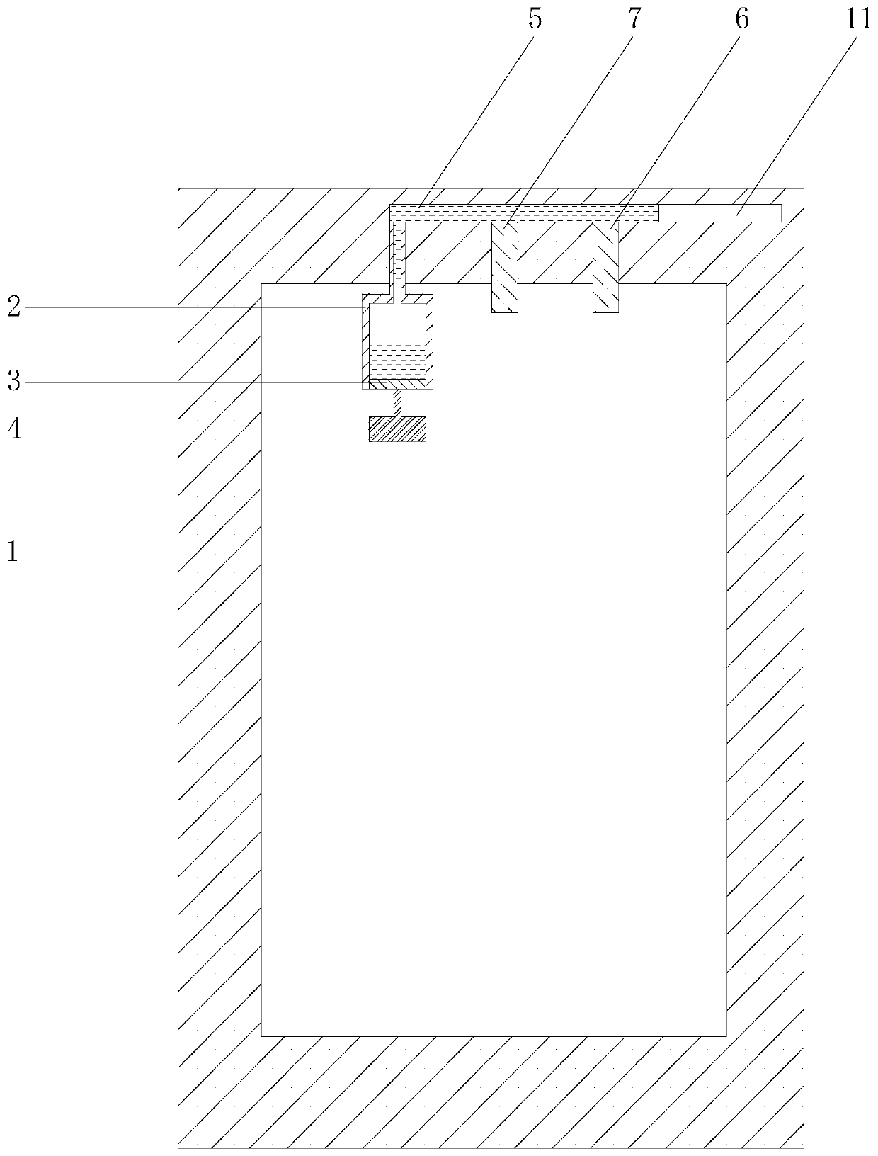
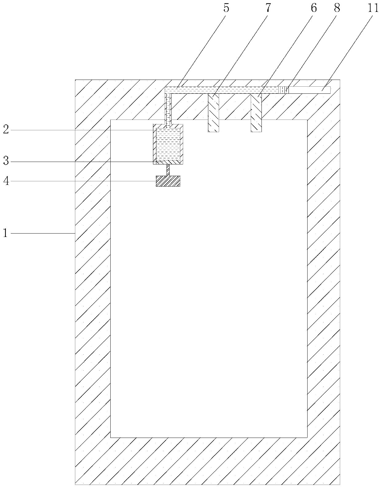
[0012] see figure 1 , is a schematic structural diagram of a liquid antenna assembly provided by an embodiment of the present application. The antenna assembly is used in electronic equipment, wherein the electronic equipment includes mobile terminals such as mobile phones and tablet computers. Such as figure 1 As shown, the liquid antenna assembly in...


PUM


Abstract

The invention relates to the technical field of terminals, and particularly relates to a liquid antenna assembly and electronic equipment thereof. Conductive liquid is used as an antenna radiator so as to reduce clearance required for a mobile phone antenna. A power output source drives a piston to move in a liquid storage tank and the conductive liquid in the liquid storage tank flows into or outof the cavity so as to change the length of the conductive liquid as the antenna radiator in the cavity, adjust the frequency band of the liquid antenna, reduce the extra insertion loss caused by adjusting the frequency band of the antenna by the antenna switch or the tuner and improve the performance of the antenna.

Description

technical field [0001] The present application relates to the technical field of terminals, in particular to a liquid antenna assembly and electronic equipment thereof. Background technique [0002] At present, with the application of full-screen in the field of mobile phones, the headroom size of mobile phone antennas is getting smaller and smaller, resulting in narrower and narrower bandwidths for mobile phones using traditional antennas. At the same time, due to the increase in communication frequency bands, it is necessary to cover all frequency bands. The state of the antenna used Or the number of antennas is increasing, which will also require more headroom size. In addition, a traditional antenna uses an antenna switch or a tuner to adjust the operating frequency band of the antenna, but the antenna switch or tuner will bring additional insertion loss, which will reduce the performance of the antenna. Contents of the invention [0003] Embodiments of the present ap...

Claims


Application Information

Patent Timeline
Patent Type & Authority Applications(China)
IPC IPC(8): H01Q1/24H01Q1/36H01Q5/314H01Q5/321
CPCH01Q1/242H01Q1/364H01Q5/314H01Q5/321
Inventor 周林张宪华
Owner OPPO CHONGQING INTELLIGENT TECH CO LTD
Why Eureka
Try Eureka