Oil-impregnated sintered bearing and method for manufacturing same

A bearing and bearing hole technology, applied in the direction of bearings, shafts and bearings, bearing components, etc., can solve the problems of sand sticking and supply, etc.

Active Publication Date: 2019-08-23
DIAMET CORP
View PDF7 Cites 2 Cited by
  • Summary
  • Abstract
  • Description
  • Claims
  • Application Information

AI Technical Summary

Problems solved by technology

[0010] Patent Document 1 does not describe the specific air permeability of the surface formed by the rough part and other surfaces, but if the air permeability of Patent Document 2 is at the level described in Patent Document 2, it is difficult to achieve the desired air permeability during high-speed rotation or the like. Sufficient oil is supplied during the operation of the bearing and the leakage of oil from the sliding surface is suppressed, and there may be sand sticking, etc.

Method used


Image

  • Oil-impregnated sintered bearing and method for manufacturing same
  • Oil-impregnated sintered bearing and method for manufacturing same
  • Oil-impregnated sintered bearing and method for manufacturing same

Examples


no. 1 Embodiment approach

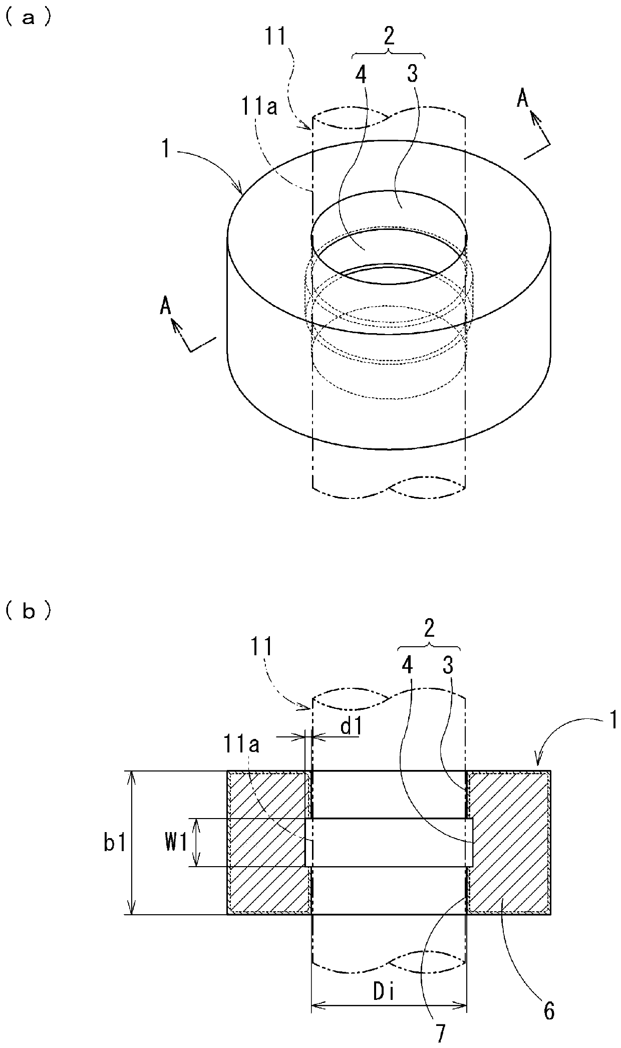
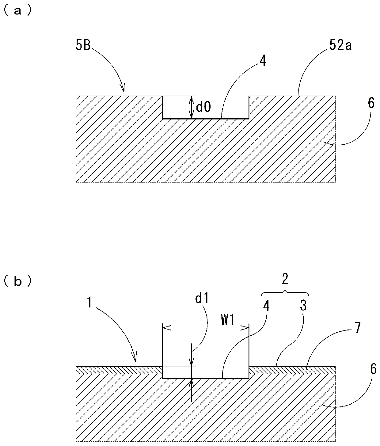
[0056] The sintered oil-impregnated bearing 1 of the first embodiment is a cylindrical bearing formed of a sintered body of metal powder, such as figure 1 and figure 2 As shown, on the inner peripheral surface of the bearing hole 2, the sliding surface 3 for supporting the outer peripheral surface 11a of the shaft 11 is formed adjacent to the axial direction of the bearing hole 2, and the diameter is larger than the diameter of the sliding surface 3 and is in contact with the shaft. The oil supply surface 4 of the gap is formed between the outer peripheral surfaces 11a of 11.

[0057] The bearing hole 2 rotatably supports the inserted shaft 11 , and the sliding surface 3 is formed such that its inner diameter is slightly larger than the outer diameter of the shaft 11 . In addition, the inner diameter Di of the sliding surface 3 is formed to be 1 mm to 30 mm, and a gap of, for example, 0.05% to 0.6% of the inner diameter Di of the sliding surface 3 is formed between the slidi...

no. 2 Embodiment approach

[0085] The sintered oil-impregnated bearing of the second embodiment is also a cylindrical bearing formed of a sintered body of metal powder, such as Figure 10 and Figure 11 As shown, on the inner peripheral surface of the bearing hole 102, a sliding surface 103 for supporting the outer peripheral surface 11a of the shaft 11 is formed adjacent to the axial direction of the bearing hole 2, and the diameter is larger than the diameter of the sliding surface 103 and is in contact with the shaft. The oil supply surface 104 of the gap is formed between the outer peripheral surfaces 11a of 11.

[0086] The bearing hole 102 rotatably supports the inserted shaft 11 , and the sliding surface 103 is formed such that its inner diameter is slightly larger than the outer diameter of the shaft 11 . In addition, the inner diameter Di of the sliding surface 103 is formed to be 1 mm to 30 mm, and a gap of, for example, 0.05% to 0.6% of the inner diameter Di of the sliding surface 103 is for...

Embodiment

[0112] The test results conducted to verify the effects of the present invention will be described.

[0113] In the test, iron-copper-based powder obtained by mixing iron, copper, tin, graphite, and the like was used as the raw material powder. As the raw material powder composed of iron-copper powder, 50% by mass of copper powder, 2% by mass of tin powder, 5% by mass of copper-phosphorus powder, 10% by mass of copper-zinc powder, graphite Adjustment was made such that the solid lubricant was 0.5% by mass and the remainder was iron powder. In addition, as for the copper powder, a flat powder having an aspect ratio of 10 or more and a maximum diameter of 1 μm to 100 μm is used, and a granular powder having an average particle diameter of 5 μm or more and 100 μm or less is used. The mixing ratio of the flat powder in was set to 25% by mass. In addition, the average particle diameter of the iron powder is the same as or larger than the average particle diameter of the granular ...


PUM

PropertyMeasurementUnit
diameteraaaaaaaaaa

Abstract

In order to provide an adequate amount of oil to a sliding surface and to prevent oil from moving from the sliding surface to the interior, thereby achieving lower friction and improving the bearing sliding characteristic, in this oil-impregnated sintered bearing (1) a sliding surface (3) supporting the outer circumferential surface of a shaft (11) and an oil supply surface (4) having a larger diameter than the sliding surface (3) are formed on the inner circumferential surface of a bearing hole (2) in which the shaft (11) is inserted, and are formed adjacent to each other in the axial direction of the bearing hole (2). The difference in height d1 between the sliding surface (3) and the oil supply surface (4) is 0.01% to 15% of the inner diameter of the sliding surface, the surface openingratio of the sliding surface (3) is 10% or less, the surface opening ratio of the oil supply surface (4) exceeds 10%, and the average equivalent-circle diameter of the openings of pores in the sliding surface is 20 mu m or less.

Description

technical field [0001] The present invention relates to a sintered oil-impregnated bearing which can be smoothly lubricated by impregnating lubricating oil inside and its manufacturing method. [0002] This application claims priority based on patent application No. 2016-249741 filed in Japan on December 22, 2016 and patent application No. 2016-249742 filed in Japan on December 22, 2016, and uses the contents thereof. Background technique [0003] The sintered oil-impregnated bearing is used in the state where the lubricating oil is impregnated in the pores. When the shaft is started, the lubricating oil seeps from the inside between the sliding surface of the shaft and the bearing, and as the shaft rotates, the lubricating oil generates pressure while supporting the shaft. Due to this lubricating property, it can be used for a long time without oil supply, so it is widely used as bearings such as bearings for vehicle-mounted motors. [0004] In such sintered oil-impregnat...

Claims


Application Information

Patent Timeline
Patent Type & Authority Applications(China)
IPC IPC(8): F16C33/14F16C17/02F16C33/10B22F1/068
CPCF16C17/02F16C33/10F16C33/14F16C33/104F16C33/145B22F3/004B22F2998/10B22F2003/166C22C1/0425C22C33/0278B22F3/03B22F3/164B22F5/106B22F1/068B22F3/02B22F3/10B22F3/16B22F3/26B22F5/10B22F7/002B22F2301/10B22F2301/35F16C33/128F16C2202/10F16C2204/10F16C2220/20
Inventor 河野肇石井义成丸山恒夫加藤纯织戸贤治
Owner DIAMET CORP
Why Eureka
Try Eureka