Supercharge Your Innovation With Domain-Expert AI Agents!

Gate drive circuit and method of operating the same

A gate drive circuit, circuit technology, applied in the field of amplifiers

Active Publication Date: 2019-08-23
ADVANCED ENERGY IND INC
View PDF22 Cites 0 Cited by
  • Summary
  • Abstract
  • Description
  • Claims
  • Application Information

AI Technical Summary

Problems solved by technology

Although vacuum technology is still used, most modern power amplifiers use three-terminal solid-state devices

Method used


Image

  • Gate drive circuit and method of operating the same
  • Gate drive circuit and method of operating the same
  • Gate drive circuit and method of operating the same

Examples


Embodiment Construction

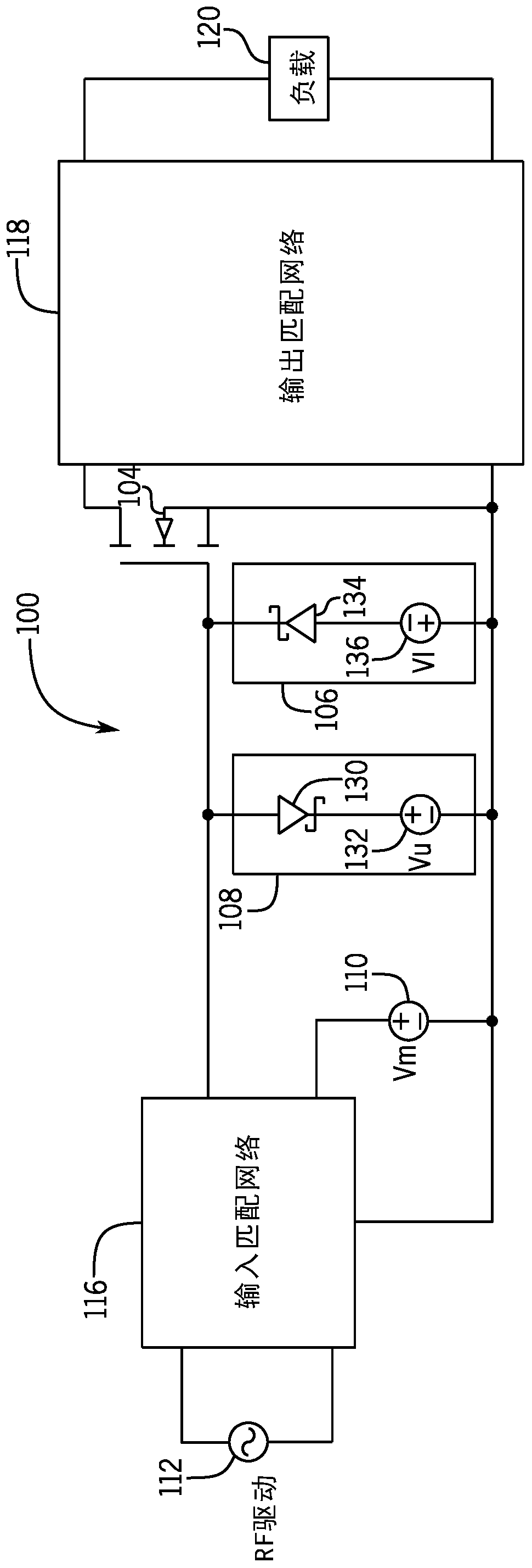
[0012] Embodiments of the present disclosure provide a gate drive circuit for controlling control signals including maximum, minimum and average voltage levels that may be applied to an input terminal (eg, gate) of a transistor. Control signals from the circuit can provide relatively efficient control of the transistor under different control conditions (eg, changes in load, changes in control frequency, changes in ambient conditions, etc.). This gate drive circuit is particularly useful for certain types of transistors, such as Gallium Nitride (GaN) High Electron Mobility Transistor (HEMT) transistors, which have a breakdown voltage relatively close to their turn-on voltage.

[0013] Transistors have been used to implement switching applications in which transistors are manipulated in their off and saturated states. Switching applications have typically been implemented using Metal Oxide Field Effect Transistor (MOSFET) devices; however, the performance of MOSFETs for these s...


PUM


Abstract

A gate drive circuit includes a lower limit clamping circuit, an upper limit clamping circuit, and an averaging circuit. The lower limit clamping circuit clamps the input node of a transistor at a minimum voltage with respect to the common node of the transistor, while the upper limit clamping circuit clamps the input node of the transistor at a maximum voltage with respect to the common node of the transistor and the averaging circuit sets the average voltage of the input node with respect to the common node over a specified period of time. The transistor includes a common node, an output node and an input node which receives the input signal. Controlling the upper limit, lower limit and average value in conjunction with fast transitions between the lower and upper limits controls the duty cycle of the input signal.

Description

[0001] Cross References to Related Applications [0002] This Patent Cooperation Treaty (PCT) patent application relates to and claims priority to U.S. Nonprovisional Application No. 15 / 374,242, filed December 9, 2016, entitled "Gate Drive Circuit and Method of Controlling It," the entire contents of which are published in Incorporated herein by reference for all purposes. technical field [0003] Aspects of the present disclosure relate to amplifiers, and in particular, to a gate driving circuit and a method of controlling the same. Background technique [0004] An amplifier is a device that enables an input signal to control power from a source independent of the signal, and is therefore capable of delivering an output signal that has some relationship to, and is usually greater than, the input signal. For power amplifiers, the main considerations are output power and efficiency. While vacuum technology is still used, most modern power amplifiers use three-terminal solid...

Claims


Application Information

Patent Timeline
Patent Type & Authority Applications(China)
IPC IPC(8): H03F1/02H03F3/195H03F3/213H03K3/017H03K3/80H03K5/08H03K17/567H01L29/20H01L29/778
CPCB64C11/02B64C11/06B64C11/325B64C27/57B64C29/0025B64C39/024B64D35/00H03K17/0812H03F3/193H03F3/2171H03F3/265H03F2200/534H03F2200/541H03F2200/222H03F2200/387H03F2200/451B64C27/14B64C27/32H03F3/2176H03K17/08122H03K17/302H03K17/693B64U10/25B64U10/13B64U10/10B64U30/20H03F3/213H03K3/017H03K5/08
Inventor G·J·J·范齐尔
Owner ADVANCED ENERGY IND INC
Features
  • R&D
  • Intellectual Property
  • Life Sciences
  • Materials
  • Tech Scout
  • Unparalleled Data Quality
  • Higher Quality Content
  • 60% Fewer Hallucinations
Learn More