Tissue engineering interbody fusion cage for cervical vertebra and using method

An intervertebral fusion device and tissue engineering technology, which is applied in the field of tissue engineering cervical intervertebral fusion device, can solve problems affecting fusion quality and long-term effect, affecting radiological examination, and bone fusion cannot be judged, etc., to achieve good fusion Quality and long-term effect, facilitate bone healing, achieve bone healing effect

Inactive Publication Date: 2019-08-27
熊海阔
View PDF0 Cites 0 Cited by
  • Summary
  • Abstract
  • Description
  • Claims
  • Application Information

AI Technical Summary

Problems solved by technology

[0005] Metal material intervertebral fusion cages have poor tissue compatibility with human bone. During arthroplasty, fretting and generation of fine debris between the interfaces are inevitable. The loosening of the interface can eventually lead to failure of bone graft fusion, nonunion and long-term pain; The elastic modulus of the intervertebral fusion cage is too high. The elastic modulus of the titanium metal intervertebral fusion cage is about 110GPa, which does not match the elastic modulus of human vertebrae (the elastic modulus of cortical bone is 2.4GPa, and the elastic modulus of cancellous bone is 2.1GPa). Stress shielding effect occurs, and the osteoporosis of adjacent vertebral bodies in the later stage leads to the subsidence of the fusion cage and the loss of intervertebral height, thus affecting the fusion quality and long-term effect; in addition, an obvious disadvantage of the metal intervertebral fusion cage is that it affects radiology. Inspection, postoperative judgment of bone graft fusion effect can only be through dynamic photography, but cannot be directly observed, and the bone fusion situation cannot be judged
[0006] The intervertebral fusion device made of carbon fiber material is more brittle and can easily cause damage to the device, which in turn can cause histological reactions; separation of carbon fibers can cause intra-articular contamination, synovitis, and spread of lymph nodes
[0007] In summary, it can be seen that the intervertebral fusion devices in the prior art are not ideal from the perspective of biomechanics and physiology, and there is no perfect solution. This technical problem has been perplexing those skilled in the art.

Method used


Image

  • Tissue engineering interbody fusion cage for cervical vertebra and using method
  • Tissue engineering interbody fusion cage for cervical vertebra and using method
  • Tissue engineering interbody fusion cage for cervical vertebra and using method

Examples


Embodiment 1

[0040] Embodiment 1 A kind of tissue engineering cervical intervertebral fusion device

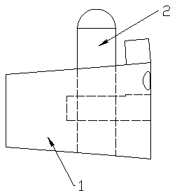
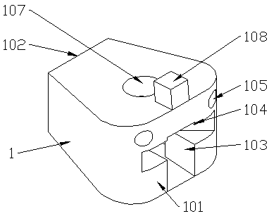
[0041] Such as Figure 1-8 Commonly shown, the present invention provides a tissue engineering cervical intervertebral fusion device, including a fusion device body 1, the inside of the fusion device body 1 is pierced with a stud 2 for insertion into the vertebral body for fixation, and the stud 2 is self-locking Inside the fusion device body 1; the fusion device body 1 and the stud 2 are porous scaffolds formed by 3D printing of absorbable medical polymer materials.

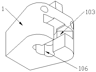
[0042]The shape of the fusion device body 1 is a wedge-shaped structure suitable for the angle of the cervical spine. The fusion device body 1 includes a front end surface 101 and a rear end surface 102. The height of the front end surface 101 is greater than the height of the rear end surface 102; Hole 103, the adjustment hole 103 extends horizontally from the front end surface 101 to the inside of the fusion device body 1...

Embodiment 2

[0044] Embodiment 2 A method of using tissue engineering cervical intervertebral fusion device

[0045] Include the following steps:

[0046] Step 1: Use absorbable medical polymer materials to 3D print the porous scaffold of fusion cage body 1 and post plug 2 according to the pre-set specifications and models, and load matrix materials that induce bone regeneration or cartilage regeneration into the scaffold; Make the scaffold produce micropores suitable for bone cells to grow into; take the patient's bone marrow stromal stem cells and load them into the scaffold for stem cell induction culture; no matter whether the cage for osteoinduction or cartilage induction culture is placed in the intervertebral space, it will grow towards the bone.

[0047] Step 2: Process a groove and a hole on the vertebral body on the adjacent side where the intervertebral fusion device is pre-installed with an instrument. The position and shape of the groove match the positioning protrusion 108, t...


PUM

PropertyMeasurementUnit
elastic modulusaaaaaaaaaa

Abstract

The invention discloses a tissue engineering interbody fusion cage for cervical vertebra and a using method. The fusion cage comprises a fusion cage body, wherein a column plug penetrates through theinterior of the fusion cage body for being inserted into a vertebra body and fixing, the column plug is self-locked in the fusion cage body, and one end face of the fusion cage body is provided with an adjusting hole for adjusting the column plug; the fusion cage body and the column plug are porous scaffolds made from an absorbable biomedical polymer material and formed through three dimensional printing. The tissue engineering interbody fusion cage for the cervical vertebra has the advantages that good bone-formation property is realized, and intervertebral bony union is facilitated; the installation is firm and stable, the self-locking function is realized, and neck anterior fixation is not needed in the installation process; no foreign bodies are left in the body after the installation,a stable environment is provided for the fusion of the vertebra body, good fusion quality and long-term effects are realized, and imaging evaluation is not influenced.

Description

technical field [0001] The invention relates to the field of tissue engineering bone, in particular to a tissue engineering cervical intervertebral fusion device and a use method thereof. Background technique [0002] Intervertebral fusion has been used as a treatment method for spinal diseases and trauma for decades. The concept of early intervertebral fusion was the stripping of a large number of muscles, sufficient autologous bone transplantation, and long-term absolute bed rest. Because intervertebral fusion reconstructs the anterior and middle columns of the spine, it greatly improves the treatment effect of spinal degenerative diseases and trauma, and intervertebral fusion has been widely used in a short period of time. It can be said that intervertebral fusion is a breakthrough in the history of spinal surgery. milestone. Although the healing rate of traditional autologous iliac crest graft is high, its complications are a problem that cannot be ignored. According to...

Claims


Application Information

Patent Timeline
Patent Type & Authority Applications(China)
IPC IPC(8): A61F2/44A61F2/30
CPCA61F2/30771A61F2/30942A61F2/4455A61F2002/3006A61F2002/30062A61F2002/30281A61F2002/30329A61F2002/30622A61F2002/30784A61F2002/3093A61F2002/30985
Inventor 熊海阔
Owner 熊海阔
Why Eureka
Try Eureka