Magnetic particle regulation and control aggregation system in space
A magnetic particle, in-space technology, applied in the direction of drug devices, other medical devices, etc., to achieve the effects of controllable movement trajectory, variable movement speed, and adjustable force
- Summary
- Abstract
- Description
- Claims
- Application Information
AI Technical Summary
Problems solved by technology
Method used
Image
Examples
Embodiment 1
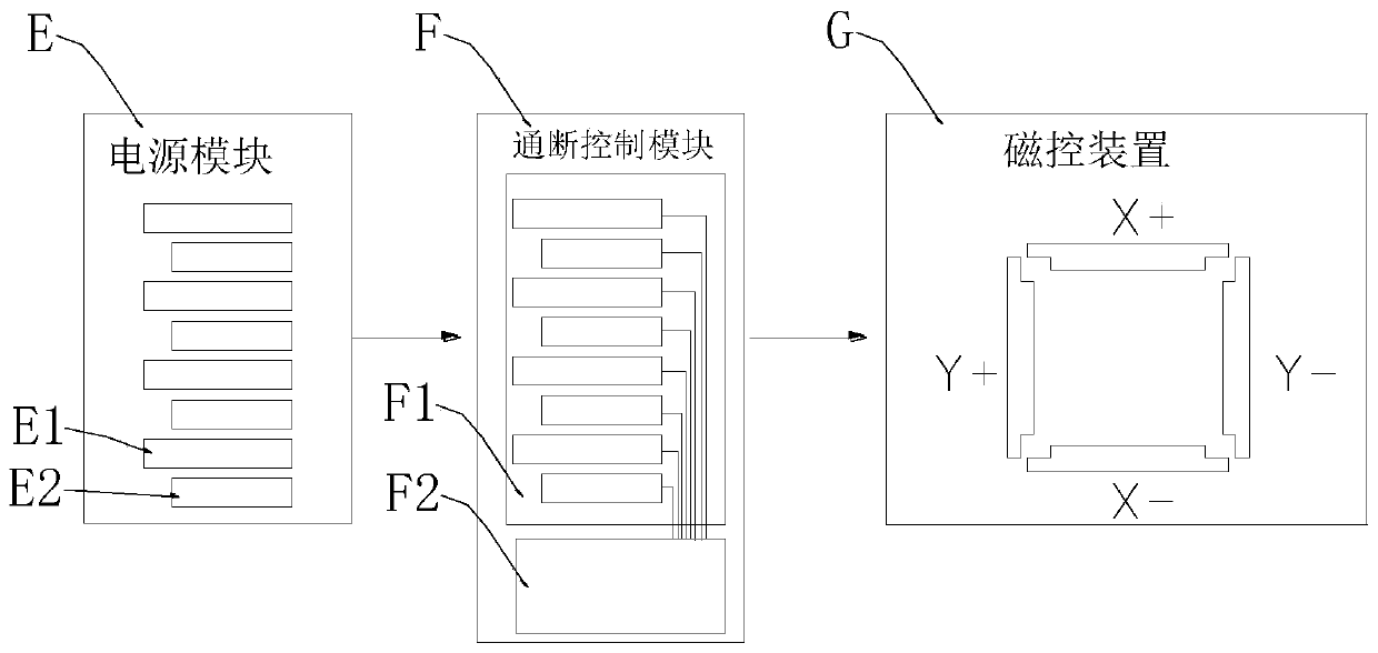
[0061] Such as figure 1 As shown, a system for regulating and aggregating magnetic particles in space is characterized in that:
[0062] It includes a power supply module E, an on-off control module F and a magnetic control device G, wherein the input end of the power supply module E is provided with a mains interface, and the output terminal group of the power supply module E passes through the on-off control module F to the magnetic control device G. The control device G is powered by time-sharing and divisional voltage;
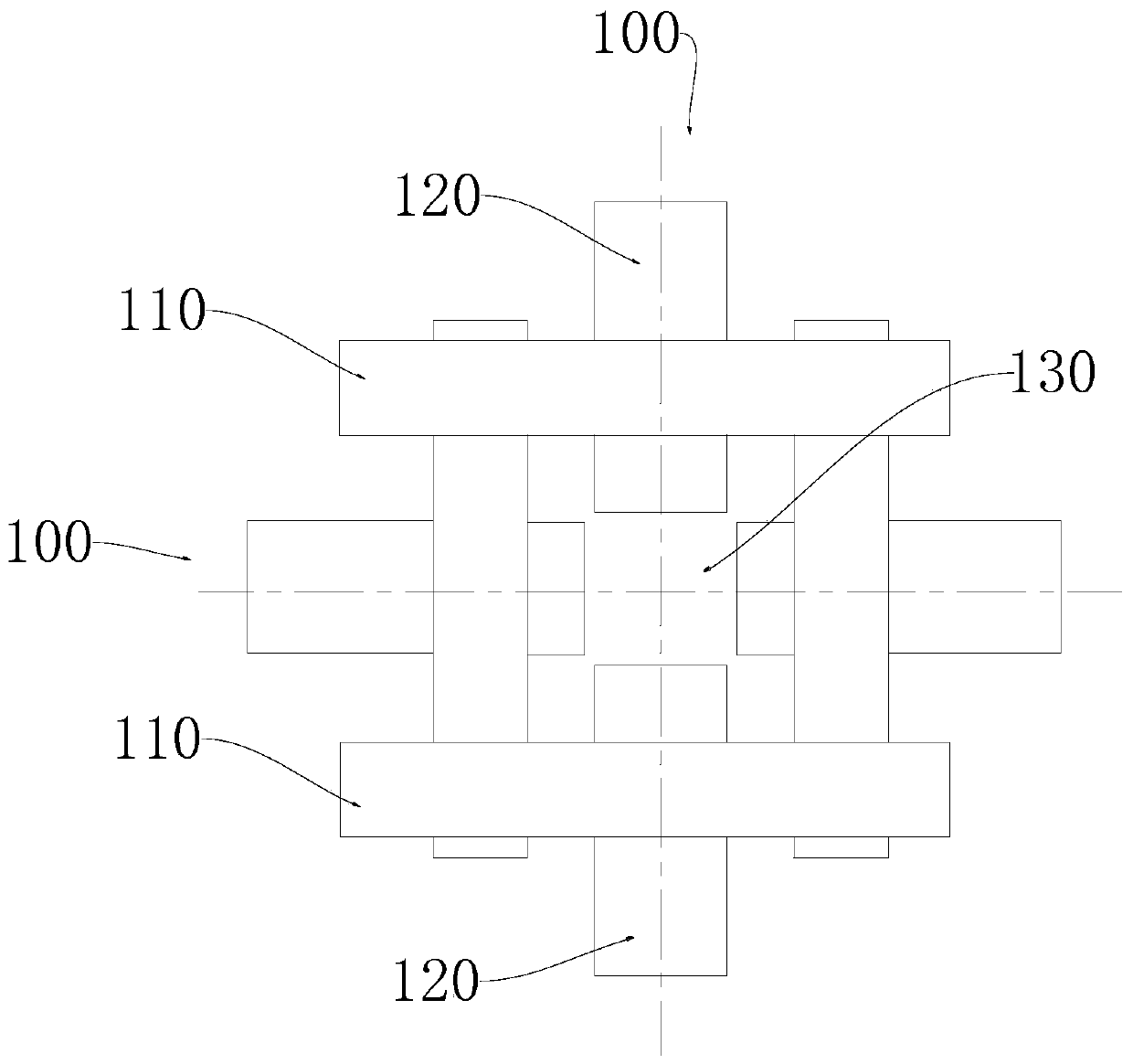
[0063] Such as Figure 2-5 As shown, the magnetic control device G includes two pairs of coil pairs 100, and a pair of the coil pairs 100 includes two sets of polarized coil groups, and one set of the polarized coil groups includes two sub-coils;
[0064] The two sub-coils of the same group are arranged in parallel and face to face, and the wires are wound in the same direction; a unidirectional polarization zone is formed between the two sub-coils of th...
Embodiment 2
[0108] figure 2 and 3 A planar magnetron device is shown. There are two pairs of coils 100, and the centerlines of the two pairs of coils 100 are perpendicular to each other. A cube-shaped winding formwork is provided inside, and the polarized coil groups are all wound on the winding formwork, and the push coil 120 is threaded on the surface of the corresponding winding formwork. For the convenience of expression, the centerlines of the two groups of coil pairs 100 are respectively marked as x-axis and y-axis, and then there are two polarized-pushing coil groups with opposite driving directions on the x-axis and y-axis respectively. The polarized coil groups in the four driving directions are sequentially recorded as X+ polarized coil group, X-polarized coil group, Y+ polarized coil group and Y-polarized coil group, and the driving coils in the four driving directions are sequentially recorded as X+ Push Coil, X-Push Coil, Y+ Push Coil, and Y-Push Coil. The X+ polarized c...
Embodiment 3
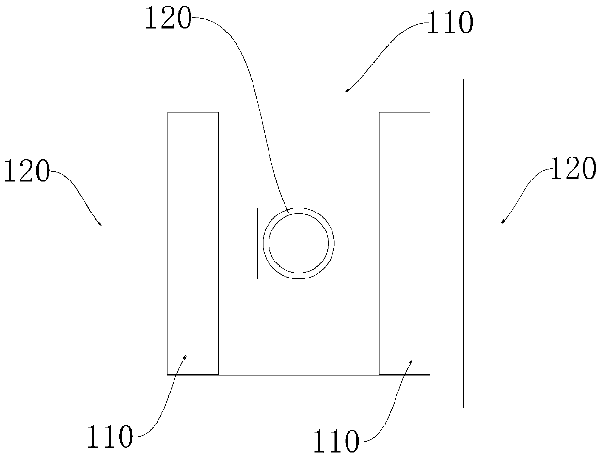
[0111] Figure 5 Shown is a three-dimensional magnetic control device. There are three groups of coil pairs 100 , the three groups of coil pairs 100 enclose the cubic magnetic control area 130 , and the centerlines of the three coil pairs 100 are perpendicular to the center of the magnetic control area 130 . A square hollow winding formwork is provided inside, and the polarized coil groups are all wound on the winding formwork, and the driving coil 120 is threaded on the surface of the corresponding winding formwork.
[0112] For the convenience of expression, the centerlines of the three groups of coil pairs 100 are respectively marked as x-axis, y-axis and z-axis, and then two polarized-push coils with opposite driving directions are respectively arranged on the x-axis, y-axis and z-axis Group. The polarized coil groups in the six driving directions are sequentially recorded as X+ polarized coil group, X-polarized coil group, Y+ polarized coil group, Y-polarized coil group...
PUM
 Abstract
Description
Claims
Application Information
 - R&D
- Intellectual Property
- Life Sciences
- Materials
- Tech Scout
- Unparalleled Data Quality
- Higher Quality Content
- 60% Fewer Hallucinations
Browse by: Latest US Patents, China's latest patents, Technical Efficacy Thesaurus, Application Domain, Technology Topic, Popular Technical Reports.
© 2025 PatSnap. All rights reserved.Legal|Privacy policy|Modern Slavery Act Transparency Statement|Sitemap|About US| Contact US: help@patsnap.com


