Method of setting minimum level width of camshaft sensor and engine electronic control system

A camshaft sensor, electronic control system technology, applied in engine control, machine/engine, electrical control, etc., can solve problems such as engine failure, error reporting of detected values, and inconsistency of minimum level width, so as to save costs and avoid false error reporting. , the effect of avoiding failures and accidents

Active Publication Date: 2019-08-30
CONTINENTAL AUTOMOTIVE CORP LIANYUNGANG CO LTD
View PDF13 Cites 0 Cited by
  • Summary
  • Abstract
  • Description
  • Claims
  • Application Information

AI Technical Summary

Problems solved by technology

[0008] 1. When the camshaft target wheel is less than 15°, the detection value of 0.6ms may report an error;
[0009] 2. During the running of the engine, the output signal level width of the camshaft sensor may change due to various practical factors, resulting in a serious discrepancy between the theoretically calculated minimum level width of the camshaft sensor and the actual output minimum level width, In this way, the engine electronic control system unit will report the following error:
[0012] 3. If it is applied to the whole vehicle, it will cause the engine to fail suddenly during driving. In the state where there is no crankshaft position sensor that can replace the camshaft position sensor, it may cause serious accidents, which will lead to a large number of recalls of the whole vehicle and ECU System software updates, resulting in huge claims

Method used

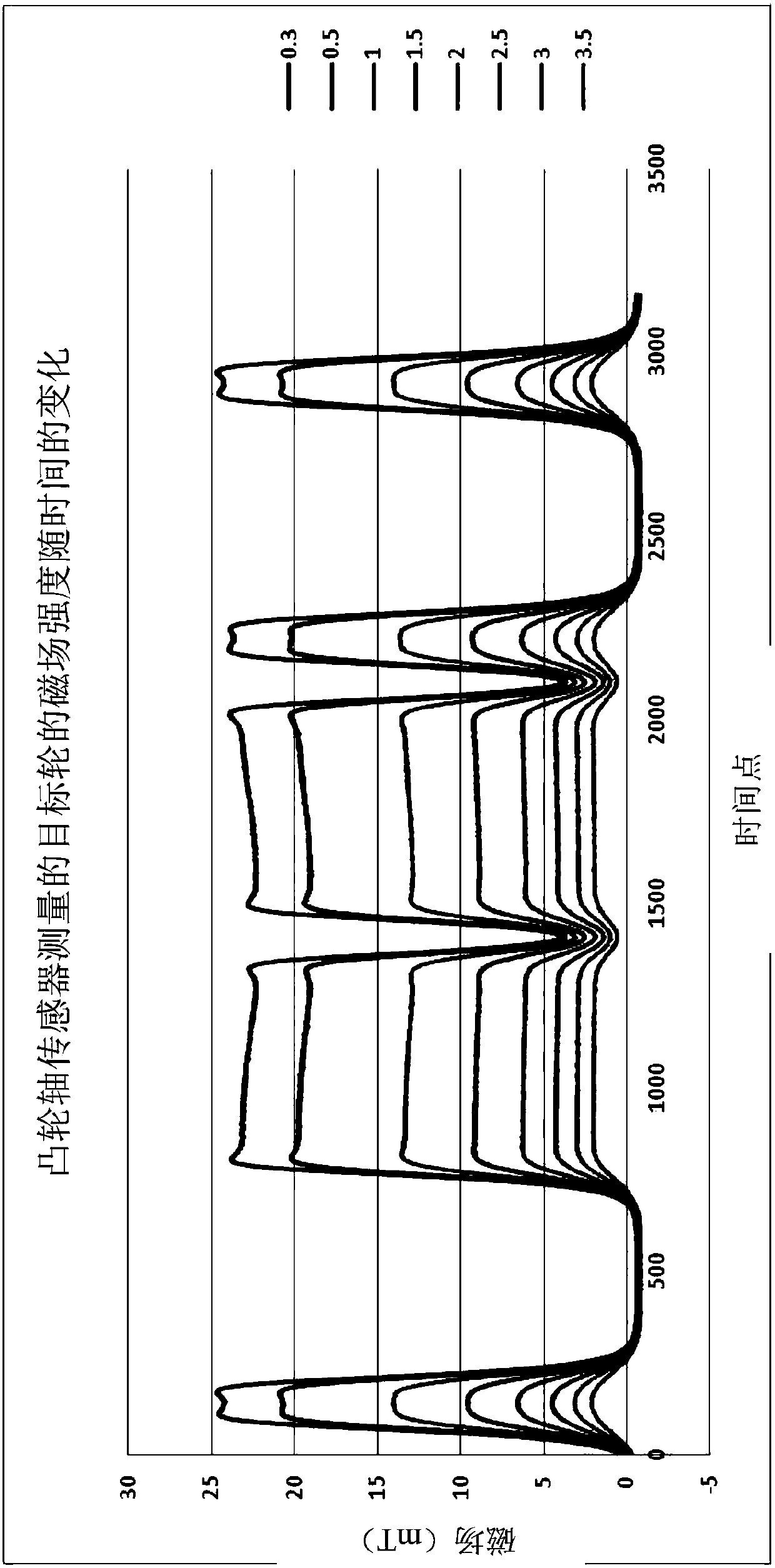
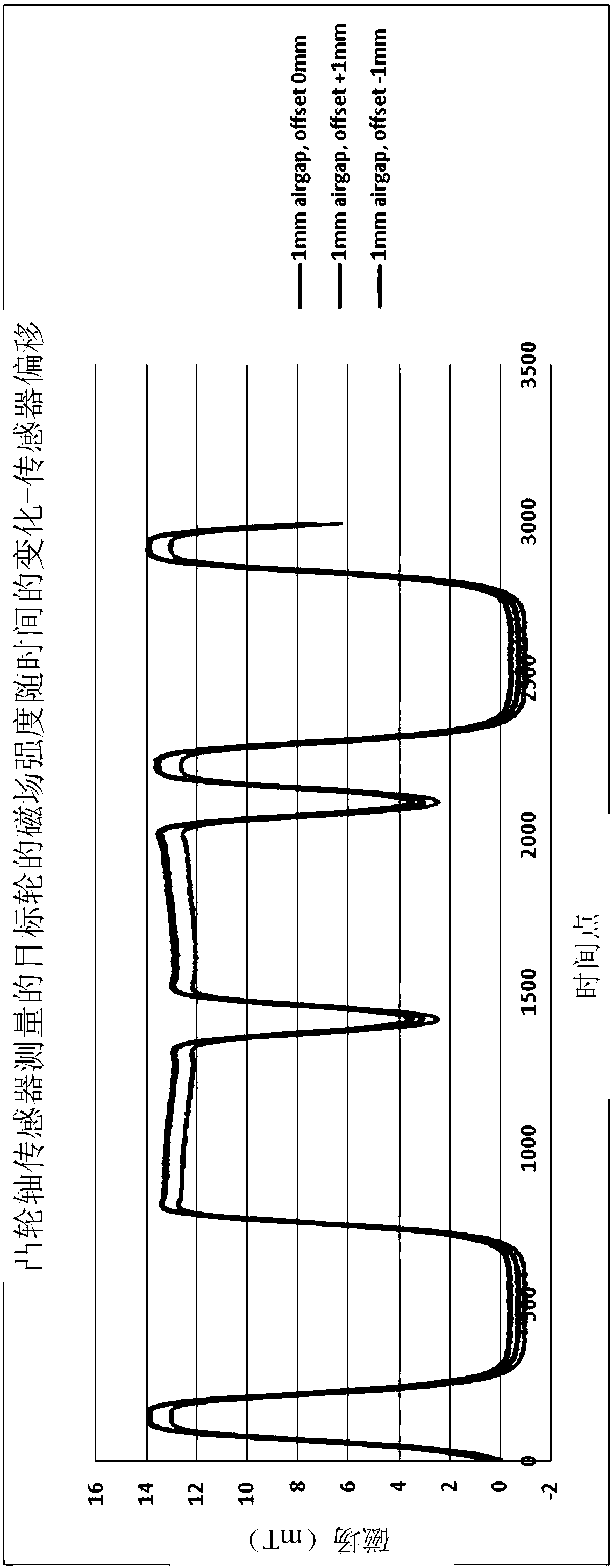
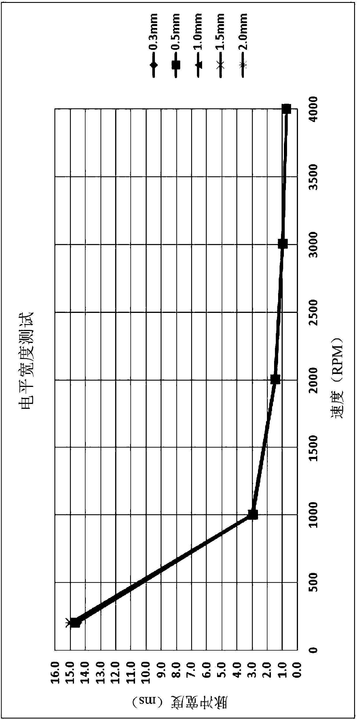

Image

  • Method of setting minimum level width of camshaft sensor and engine electronic control system
  • Method of setting minimum level width of camshaft sensor and engine electronic control system
  • Method of setting minimum level width of camshaft sensor and engine electronic control system

Examples


Embodiment Construction

[0023] Embodiments of the present invention are described below with reference to the drawings. In the following description, numerous specific details are set forth in order to enable those skilled in the art to more fully understand and practice the present invention. It will be apparent, however, to one skilled in the art that the present invention may be practiced without some of these specific details. Furthermore, it should be understood that the invention is not limited to the particular embodiments described. Rather, it is conceivable to implement the invention in any combination of the features and elements described below, regardless of whether they relate to different embodiments. Accordingly, the following aspects, features, embodiments and advantages are by way of illustration only and should not be considered elements or limitations of the claims unless explicitly stated in the claims.

[0024] The inventor realizes that during the running of the engine, the ou...


PUM


Abstract

The invention discloses a method of setting a minimum level width of a camshaft sensor in an engine electronic control system. The method comprises the following steps that in a test aiming to an engine and the camshaft sensor, changes on a width of an output signal level of the camshaft sensor are tested under different test conditions; and a minimum level width value of the camshaft sensor in the engine electronic control system is set according to the minimum width value of the output signal level of the camshaft sensor obtained by the test under different test conditions. The invention further discloses the corresponding engine electronic control system and a vehicle with the same.

Description

technical field [0001] The invention relates to the field of automobiles, in particular to a method for setting the minimum level width of a camshaft sensor in an engine electronic control system and the engine electronic control system. Background technique [0002] In the engine electronic control system (ECU), there is a strategy for monitoring the minimum level width of the output signal of the camshaft sensor: [0003] ECU (engine electronic control system software testing project) [0004] NC_T_SEG_MIN_CAM_IN (>0.6ms) [0005] NC_T_SEG_MIN_CAM_EX(>0.6ms) [0006] Due to the complex engine working conditions and more electromagnetic interference, some interference waveforms are coupled to the camshaft sensor. These interference waveforms will cause the electronic control system to mistake the signal output by the camshaft sensor, which will cause the electronic control system to make wrong judgments, implement wrong actions, and further cause the engine itself ...

Claims


Application Information

Patent Timeline
Patent Type & Authority Applications(China)
IPC IPC(8): F02D41/26G01M15/04
CPCF02D41/26G01M15/04
Inventor 张明唐翌任宏伟
Owner CONTINENTAL AUTOMOTIVE CORP LIANYUNGANG CO LTD
Why Eureka
Try Eureka