Combined non-contact double-end-face seal based on magnetic liquid sealing and fluid dynamic-pressure mechanical sealing

A magnetic fluid and fluid dynamic pressure technology, which is applied to the components of pumping devices for elastic fluids, liquid fuel engines, mechanical equipment, etc. cause accidents

Pending Publication Date: 2019-08-30
NANJING FORESTRY UNIV
View PDF3 Cites 10 Cited by
  • Summary
  • Abstract
  • Description
  • Claims
  • Application Information

AI Technical Summary

Problems solved by technology

However, there are several problems with this structure: first, during the start-stop process, the particles in the magnetic liquid on the sealing interface will aggravate the wear of the dynamic and static ring sealing end faces; second, during the stable operation, the magnetic liquid fills the entire sealing interface , if the gap between the sealing end faces suddenly decreases, it will inevitably cause the magnetic liquid to be squeezed out of the sealing interface, hang on the edge of the inner and outer diameters of the sealing surface, and even be thrown into or directly splashed into the pump chamber, polluting the molten salt medium and causing accidents; Or, the dynamic and static rings in relative motion cause the friction between the magnetic liquid at the sealing interface and the viscous shear force to generate heat, and accumulate and heat up. The increase in temperature will not only cause the deformation of the sealing ring, but also cause the magnetic force to drop. , affecting the sealing ability of the magnetic liquid seal

Method used


Image

  • Combined non-contact double-end-face seal based on magnetic liquid sealing and fluid dynamic-pressure mechanical sealing
  • Combined non-contact double-end-face seal based on magnetic liquid sealing and fluid dynamic-pressure mechanical sealing
  • Combined non-contact double-end-face seal based on magnetic liquid sealing and fluid dynamic-pressure mechanical sealing

Examples


Embodiment Construction

[0056] In order to describe the above-mentioned features and advantages of this patent more clearly, the specific implementation manners of this patent will be further described below in conjunction with the accompanying drawings.

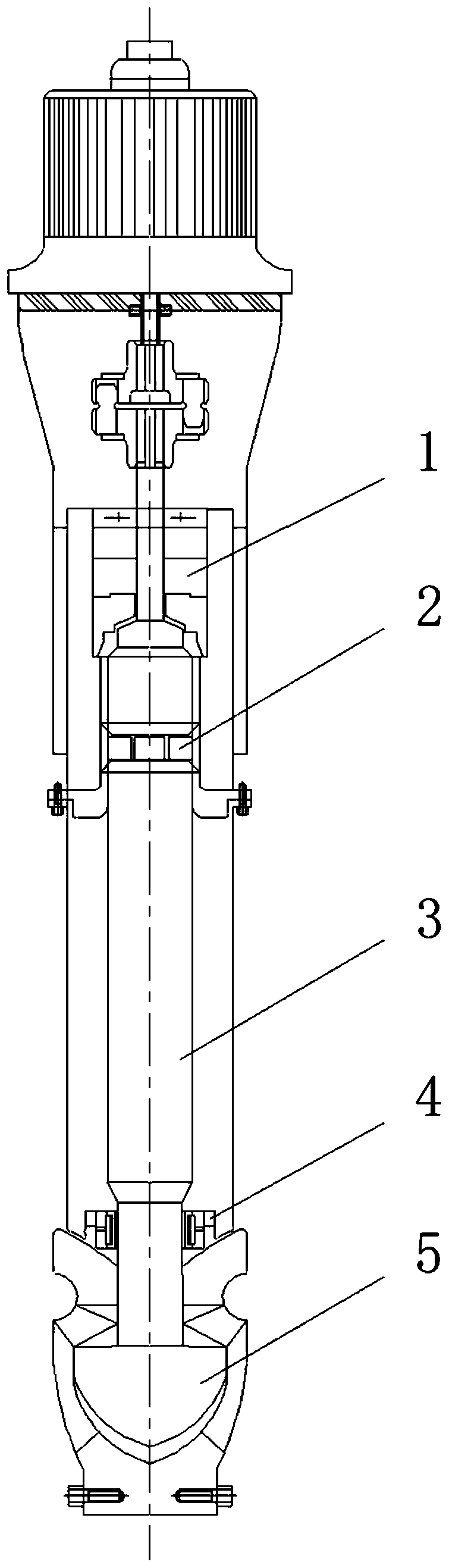
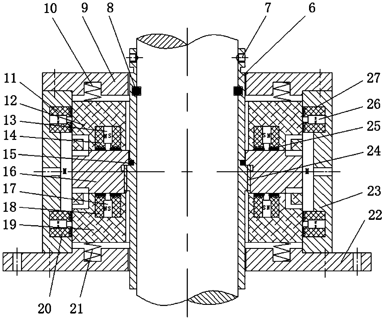
[0057] Figure 2 to Figure 7 A combined non-contact double-end seal based on a magnetic liquid seal and a hydrodynamic mechanical seal is described. It is used to seal the gap between the main pump shaft and the shell of the molten salt reactor, which can ensure the molten salt pump Zero leakage and long-term safe and stable operation of the shaft seal.

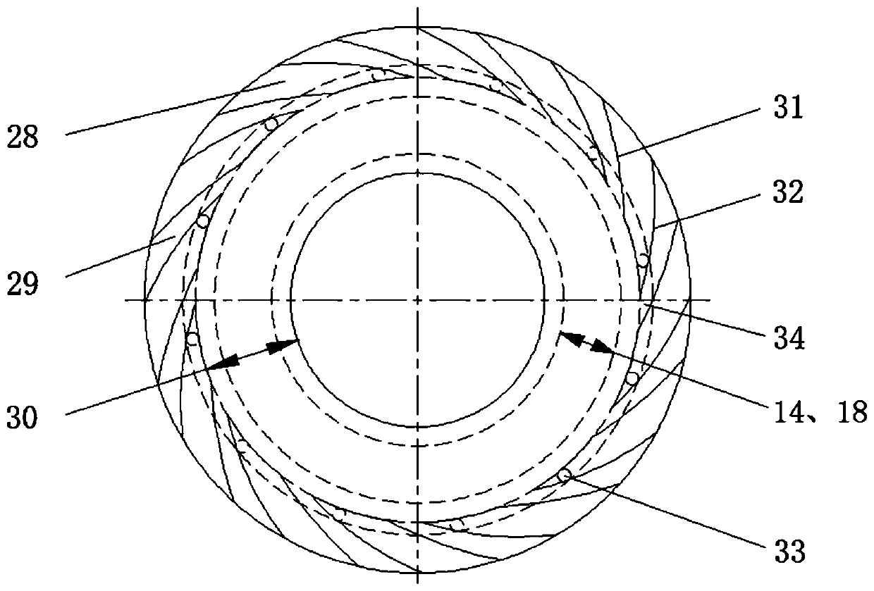
[0058] The structure of the upper and lower ends of the moving ring 16 is arranged symmetrically with the middle section M-M of the moving ring. Each end surface includes three parts: a spiral groove 28, a sealing weir 29 and a sealing dam 30. The spiral grooves 28 are evenly distributed on the outer diameter side of the end surface of the moving ring. The inner diameter side of the end face is a...


PUM


Abstract

The invention provides a combined type non-contact double-end-face seal based on magnetic liquid sealing and fluid dynamic-pressure mechanical sealing, so that the zero leakage and the long-period safe and stable operation of the molten salt pump shaft seal can be guaranteed. The combined type non-contact double-end-face seal is arranged between a shell and a rotary shaft of the rotary equipment,the combined non-contact double-end-face seal is composed of "a pumping-in type" fluid dynamic-pressure mechanical seal and a magnetic liquid seal, the upper end surface and the lower end surface of movable rings are movable ring sealing end surfaces, each movable ring sealing end surface is provided with a groove table area and a sealing dam, and the groove table area is provided with uniformly distributed spiral grooves; a current collecting ring groove is located on the outer diameter side of a sealing end surface, the drainage hole channel is used for communicating the current collecting ring groove with a blocking fluid cavity, and a magnetic generating mechanism is located at the inner diameter side part of the sealing end surface; when the movable rings rotate relative to static rings, the spiral grooves are pumped into blocking fluid, the opening force of the end face is generated, the sealing end face is separated, at the moment, the opening distance delta of the end face formed by the fluid dynamic pressure and the distance d between the pole shoe and the end face of the static rings form an operation state magnetic liquid sealing clearance d+delta.

Description

technical field [0001] This patent belongs to the technical field of mechanical seals, and relates to self-pumping fluid dynamic pressure mechanical seals and magnetic liquid seal technologies, and is especially suitable for the seal between the rotating shaft and the casing of a gas protection pump or compressor. Background technique [0002] Since the beginning of this century, due to the increasingly serious shortage of energy and resources worldwide, and related environmental issues such as the greenhouse gas effect have become increasingly prominent, the search for sustainable, safe, stable and environmentally friendly energy has attracted the attention of all countries. In 2002, the policy group of the Generation IV Nuclear Energy International Forum (GIF) released a technology roadmap, proposing six types of reactors accepted by almost all nuclear energy countries, three of which are sodium-cooled fast reactors, lead-cooled fast reactors and gas-cooled reactors. Fast ...

Claims


Application Information

Patent Timeline
Patent Type & Authority Applications(China)
IPC IPC(8): F04D29/10F04D29/12F04D29/58
CPCF04D29/106F04D29/108F04D29/126F04D29/5893
Inventor 孙见君马琳博全琴葛诚马晨波於秋萍
Owner NANJING FORESTRY UNIV
Why Eureka
Try Eureka