Driving compensation method for rope-driving continuum robot

A compensation method and continuum technology, applied in manipulators, program-controlled manipulators, manufacturing tools, etc., can solve the problems of small size, poor versatility, and low control accuracy of robots, so as to improve motion control accuracy, reduce technical difficulty and Damage, the effect of improving control accuracy

Active Publication Date: 2019-09-03
NANJING UNIV OF AERONAUTICS & ASTRONAUTICS
View PDF9 Cites 14 Cited by
  • Summary
  • Abstract
  • Description
  • Claims
  • Application Information

AI Technical Summary

Problems solved by technology

[0003] Due to the modeling error of the continuum robot system, the friction error between the driving rope and the guide wheel, and the rebound error of the rope, the control accuracy of the end position of the continuum robot is low, which may cause tissue and organ damage. Even threatening the life of the patient, it is necessary to model and compensate the motion control system of the continuum robot to improve the control accuracy of the robot itself and ensure the safety and stability of minimally invasive interventional surgery
[0004] At present, the method of real-time tracking and feedback control of the end pose of the robot through expensive external measurement equipment to improve the position accuracy of the robot is expensive, and the continuum robot used for vascular interventional surgery is small in size, and traditional sensing equipment cannot Integrated into the robot body, poor versatility

Method used


Image

  • Driving compensation method for rope-driving continuum robot
  • Driving compensation method for rope-driving continuum robot
  • Driving compensation method for rope-driving continuum robot

Examples


Embodiment Construction

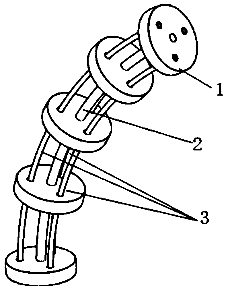
[0056] combined with figure 1 , 2 3. The technical route proposed by the present invention is specifically explained and explained. The application example here is not only applicable to this example, but also applicable to rope-driven continuum robots of various structural types.

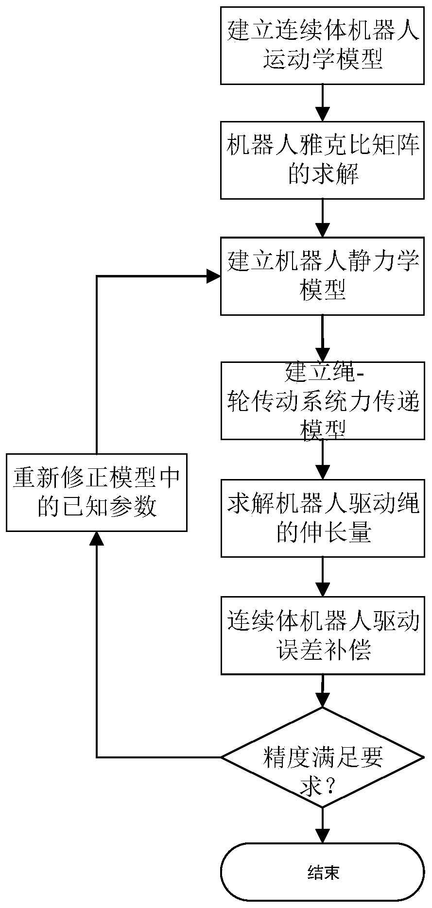
[0057] refer to figure 1 , a drive compensation method for a rope-driven continuum robot of the present invention includes the following steps:

[0058] (1) Establish the kinematics model of the continuum robot

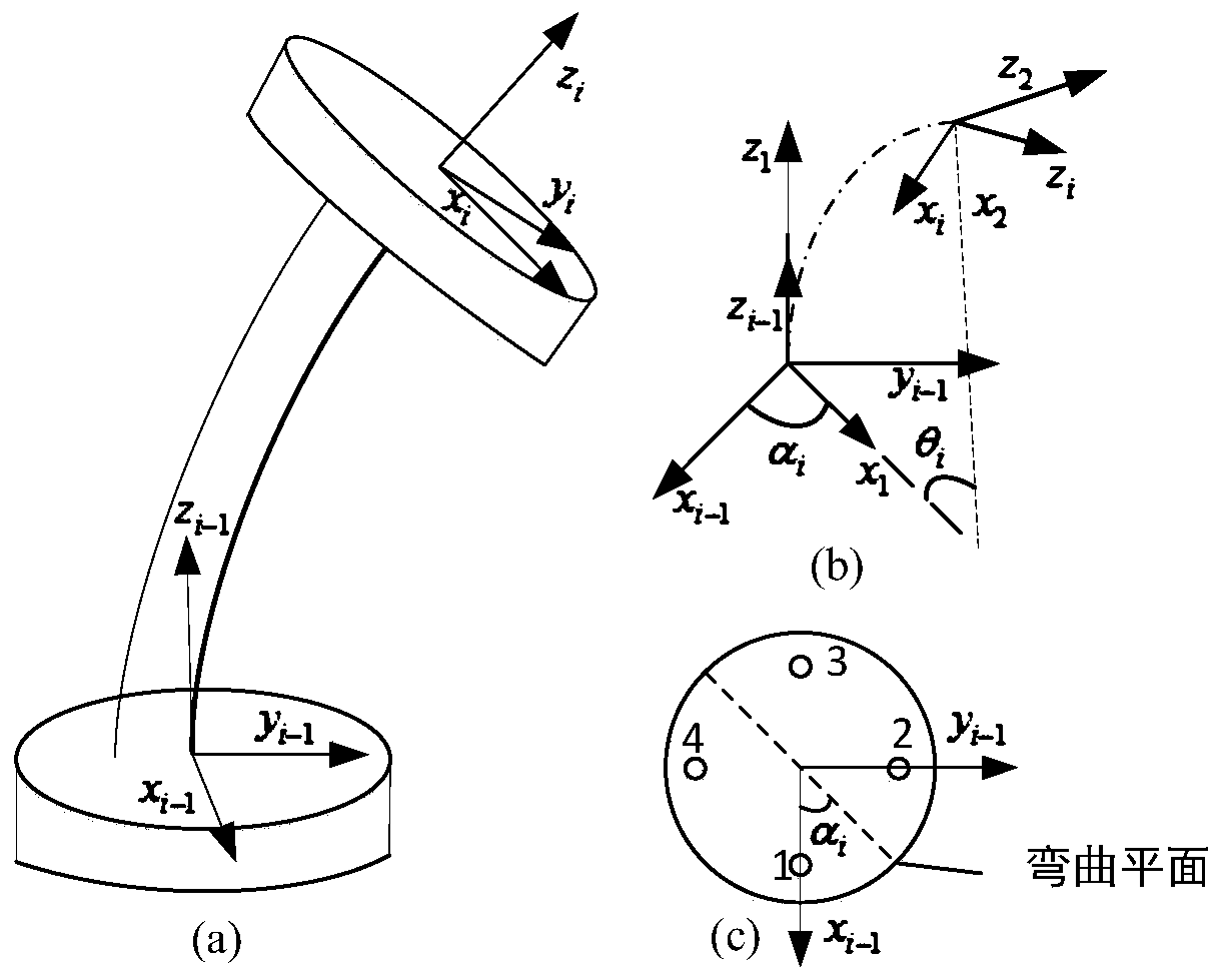
[0059] The kinematics model of the continuum robot mainly includes two parts, one is to establish the mapping relationship between the drive space and the joint space, and the other is the mapping relationship between the joint space and the operation space. The kinematics of the catheter robot can be derived through the superposition between the two. Model. The single-section bending element structure such as figure 2 As shown, the kinematic model of the continuum robot is establish...


PUM


Abstract

The invention discloses a driving compensation method for a rope-driving continuum robot. The method specifically comprises the following steps of establishing a kinematic model of the continuum robot by combining a segmented constant curvature arc hypothesis and a geometric analysis method; solving Jacobian matrix of the robot based on differential transformation principle; establishing a statics model of the robot based on virtual work principle; building a force transmission model of a rope-wheel drive system based on Coulomb friction; solving the elongation of a robot driving rope based on Hooke's law; and feeding back the driving rope length compensation amount to a control unit to realize error compensation of the transmission system of the continuum robot and improve the motion control precision of the robot. The method of has the characteristics of simplicity, high efficiency, low cost, good universality and the like, avoids using expensive measuring sensors, and realizes thepurpose of improving the motion control precision of the robot by establishing a driving error compensation model of the continuum robot system.

Description

technical field [0001] The invention relates to a drive compensation method for a rope-driven continuum robot, and relates to the technical field of continuum robot control. Background technique [0002] Continuum robots are widely used in the field of minimally invasive interventional surgery due to their unique characteristics of flexibility, flexibility and safety. Compared with the traditional rigid articulated robot, the continuum robot is a kind of robot that imitates natural creatures, such as elephant trunks, octopus tentacles, etc., and can flexibly change its shape to adapt to small and unstructured workspaces. surroundings. Interventional surgery based on continuum robots has high safety and efficiency, not only can reduce the work intensity and technical requirements of doctors, reduce the degree of radiation exposure of doctors and patients, but also improve the quality and efficiency of interventional surgery, ensuring that The success rate and precision of i...

Claims


Application Information

Patent Timeline
Patent Type & Authority Applications(China)
IPC IPC(8): B25J9/16B25J9/10
CPCB25J9/104B25J9/1605B25J9/1607
Inventor 齐飞陈柏白东明鞠锋郭昊曹燕飞张帅向立清
Owner NANJING UNIV OF AERONAUTICS & ASTRONAUTICS
Why Eureka
Try Eureka