Coreless brushless direct current motor with locking device

A brushed DC motor and locking device technology, applied in the field of hollow cup brushless DC motor with locking device, can solve the problem of difficult to meet the integration, miniaturization, multi-function, light weight, miniaturization and high performance of rudder control servo system. Dynamic response, high reliability, dynamic response of steering gear, deterioration of accuracy, reliability, limit of the maximum speed of brake, etc., to achieve the effect of increasing product protection level, good sine of back EMF, and reducing temperature rise

Pending Publication Date: 2020-09-25
杭州精导智能科技有限公司
View PDF0 Cites 4 Cited by
  • Summary
  • Abstract
  • Description
  • Claims
  • Application Information

AI Technical Summary

Problems solved by technology

However, the radial and axial dimensions of conventional electromagnetic brakes are generally large, which leads to the extension of the axial dimension of the rotor shaft system of the steering gear, which easily leads to the deterioration of the stiffness of the rotor system, especially when the rotor is running at high speed, causing vibration and noise of the steering gear. And the control is unstable, and the dynamic response, accuracy, reliability and other key variables of the steering gear will deteriorate further.
On the other hand, conventional brakes have a maximum speed limit, and the braking speed is generally below 8000rpm
In summary, the structure of the conventional reducer, motor, brake, etc., which is arranged axially according to the modular components, is difficult to meet the requirements of integration, miniaturization, multi-function, light weight, miniaturization, high dynamic response, and high reliability of the steering control servo system. Indicator requirements

Method used


Image

  • Coreless brushless direct current motor with locking device
  • Coreless brushless direct current motor with locking device
  • Coreless brushless direct current motor with locking device

Examples


Embodiment Construction

[0056] In order to make the object, technical solution and advantages of the present invention clearer, the present invention will be further described in detail below with reference to the accompanying drawings and embodiments. However, it should be understood that the specific embodiments described here are only used to explain the present invention, and are not intended to limit the scope of the present invention. Also, in the following description, descriptions of well-known structures and techniques are omitted to avoid unnecessarily obscuring the concept of the present invention.

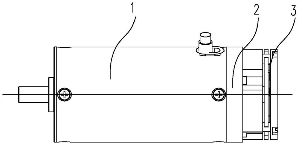
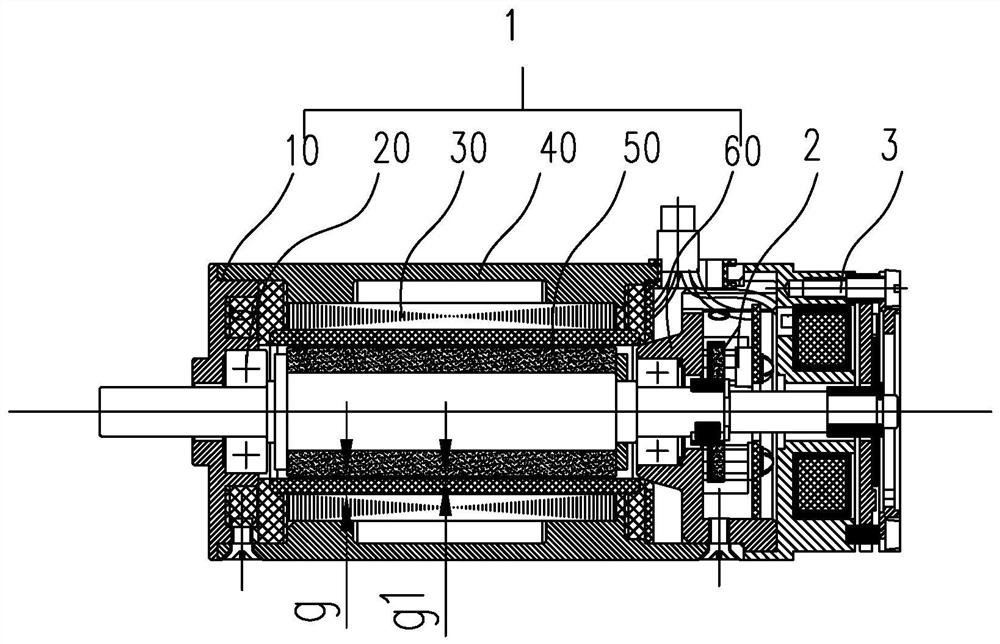
[0057] Such as Figure 1 to Figure 10 As shown, a hollow cup brushless DC motor with a lock includes a motor body (1) and a lock (3), the front part of the motor body (1) is provided with an output end, and the motor body ( 1) is provided with a locking device (3) at the rear.

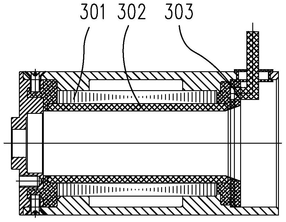
[0058] The main body of the motor adopts a hollow cup winding structure. The main body of the motor (1) realizes t...


PUM


Abstract

The invention discloses a coreless brushless direct current motor with a locking device. The motor comprises a motor main body and a locking device. An output end is arranged at the front part of themotor main body. A locking device is arranged at the rear part of the motor main body. The motor main body realizes output of torque, rotating speed and power function indexes. The motor main body iscomposed of a front end cover, a stator armature, a casing, a rotor and a rear end cover. The front end cover is arranged at the front end of the casing, the rear end cover is arranged at the rear endof the casing, the rotor is installed in the middle of the casing, and the stator armature is arranged outside the rotor in a matching manner. By optimizing the sizes of parts of the motor, the rotorposition sensor and the locking device and through the multifunctional design of the parts, the size of the motor is fully utilized, the axial and radial sizes of the motor are reduced, and product miniaturization and high power density are achieved.

Description

technical field [0001] The invention relates to the technical field of motors, in particular to a hollow cup brushless DC motor with a lock. Background technique [0002] The coreless brushless motor belongs to the DC permanent magnet servo micro motor. The main difference from the ordinary brushless DC motor is that there is no cogging on the armature core, and the motor winding is made into a cup-shaped motor according to a special winding process. . Compared with the traditional cogging motor, it has the following advantages: 1. High efficiency: the efficiency of the coreless motor is mostly above 70%, and some products are even close to 90%, while the efficiency of the traditional cogging motor is the same under the same volume and weight. Less than 70%; 2. Small size, light weight, high power and torque density: Due to the improved work efficiency and reduced loss, the power density of the coreless motor is greatly improved. Compared with the traditional cogging motor,...

Claims


Application Information

Patent Timeline
Patent Type & Authority Applications(China)
IPC IPC(8): H02K5/04H02K7/10H02K3/28H02K15/04H02K15/06H02K3/50H02K15/12H02K29/08H02K15/00H02K15/03H02K21/12
CPCH02K3/28H02K3/50H02K5/04H02K7/10H02K15/00H02K15/03H02K15/0435H02K15/06H02K15/12H02K21/12H02K29/08H02K2203/03
Inventor 唐雪华罗振生黄飞何雪刚阮景龄
Owner 杭州精导智能科技有限公司
Why Eureka
Try Eureka