Supercharge Your Innovation With Domain-Expert AI Agents!

Robot precision control method coupling kinematics and rigidity parameter identification

A kinematic parameter and parameter identification technology, which is applied in the direction of program-controlled manipulators, manipulators, manufacturing tools, etc., can solve the problems of insufficient adaptability to processing tasks, difficulty in ensuring the accuracy of offline positioning error prediction methods, etc., to improve prediction capabilities and improve operations. Accuracy, the effect of improving accuracy

Active Publication Date: 2019-09-03
NANJING UNIV OF AERONAUTICS & ASTRONAUTICS
View PDF7 Cites 18 Cited by
  • Summary
  • Abstract
  • Description
  • Claims
  • Application Information

AI Technical Summary

Problems solved by technology

[0009] In view of the deficiencies of the above-mentioned prior art, the purpose of the present invention is to provide a robot precision control method that couples kinematics and stiffness parameter identification, so as to solve the lack of adaptability of the existing robot calibration method to actual processing tasks and offline positioning error prediction The problem that the accuracy of the method is difficult to guarantee

Method used


Image

  • Robot precision control method coupling kinematics and rigidity parameter identification
  • Robot precision control method coupling kinematics and rigidity parameter identification
  • Robot precision control method coupling kinematics and rigidity parameter identification

Examples


Embodiment Construction

[0033] In order to facilitate the understanding of those skilled in the art, the present invention will be further described below in conjunction with the embodiments and accompanying drawings, and the contents mentioned in the embodiments are not intended to limit the present invention.

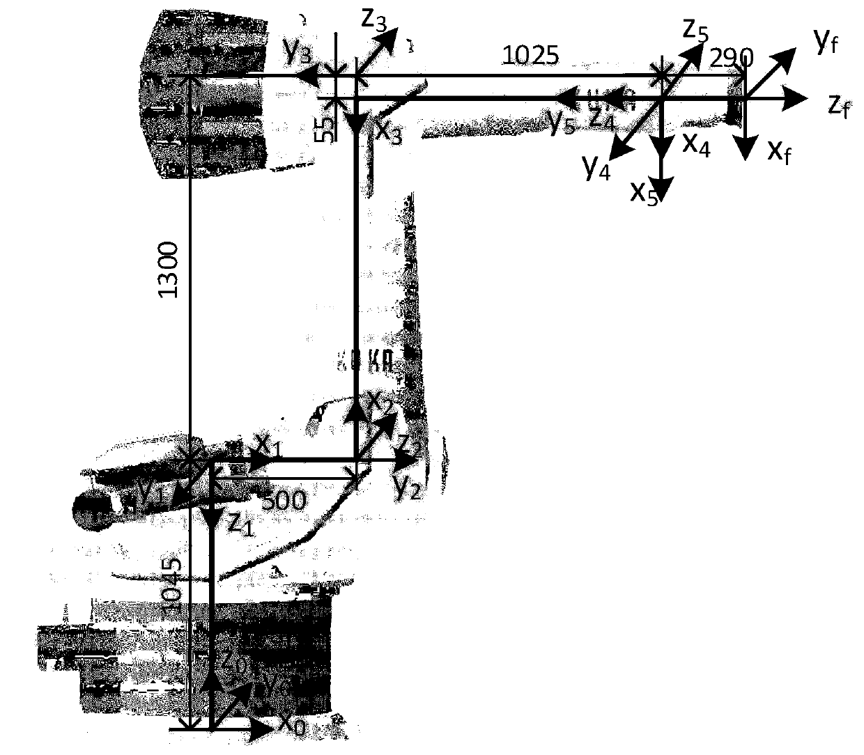
[0034] Step 1: Put the laser tracker in a suitable position for easy measurement. A laser tracker is used to measure and construct a coordinate system consisting of the robot base coordinate system Base, the flange coordinate system Flange, the tool coordinate system Tool, and the six-dimensional force sensor coordinate system Force.

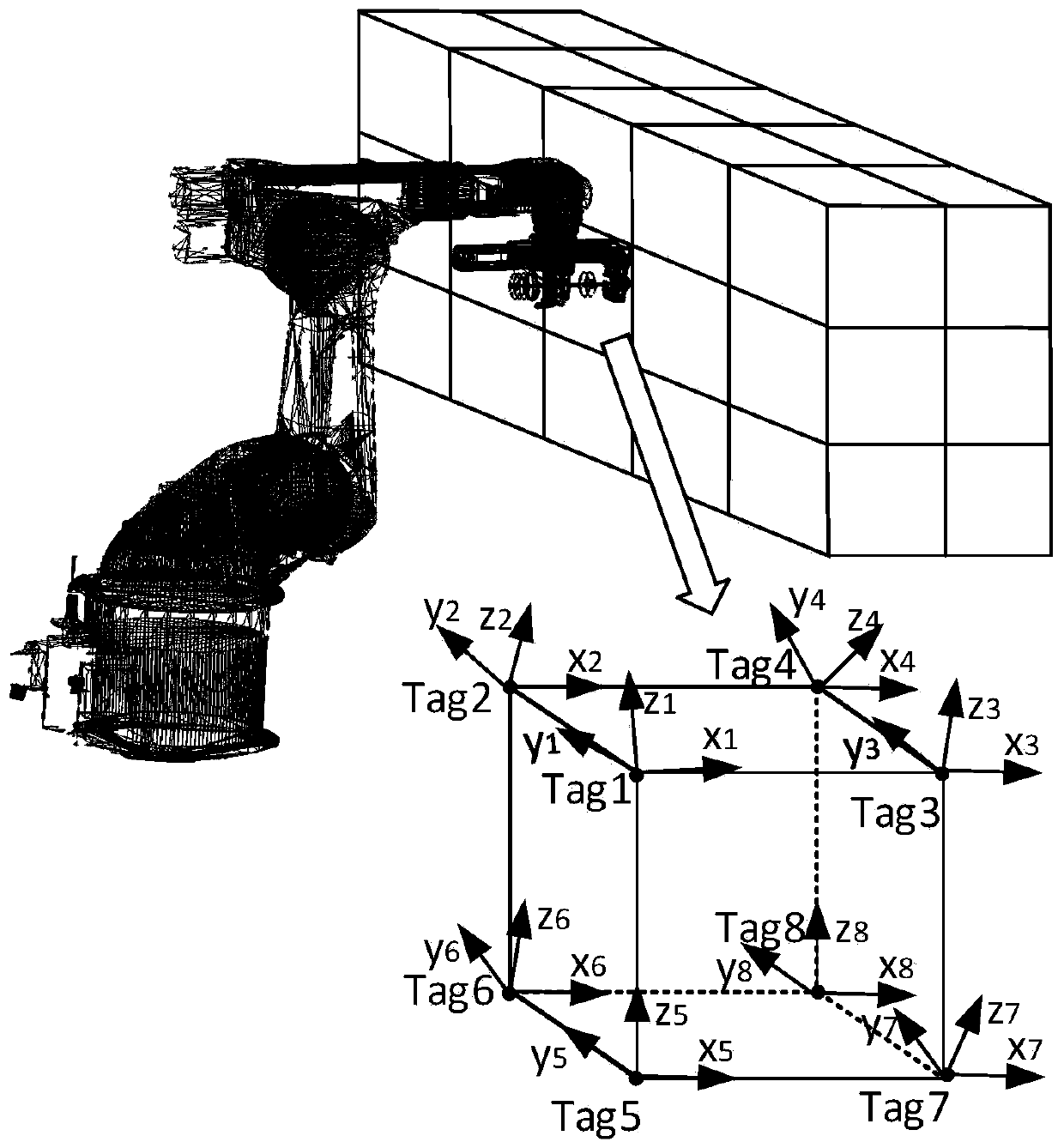
[0035] Step 2: In the effective working space of the robot, the working space is divided into a series of cubic grids according to the given grid step size, and the fixed points of the grids are used as the target positions of sampling points for kinematics and joint stiffness identification (see figure 1 In Tag1 to Tag8, where X i , Y i ,Z iare respectivel...


PUM


Abstract

The invention discloses a robot precision control method coupling kinematics and rigidity parameter identification, and belongs to the technical field of industrial robot precision compensation. The method is characterized in that errors of an industrial robot kinematics parameter correcting robot motion model are identified, robot rigidity modeling is realized through a rigidity identification method, operation load is dynamically sensed on line by combining a six-dimensional force sensor, a two-order compensation scheme for compensation for robot geometric errors and flexible errors under aload state is disclosed, and precise positioning of a robot under the working condition state is realized. The robot geometric errors and the flexible errors are precisely calculated, so that high precision control on absolute positioning errors of the robot under the processing state is realized, and technical needs of high-precision processing fields of hole-making, milling and the like of the robot are met.

Description

technical field [0001] The invention belongs to the technical field of robot precision compensation, and specifically refers to a robot precision control method coupled with kinematics and stiffness parameter identification, which can effectively improve the absolute positioning precision of a robot in an operating state. Background technique [0002] As a typical flexible and high-precision operation carrier, industrial robots have the characteristics of high operation flexibility, high degree of automation, low space requirements, and low operating costs. Cooperating with multi-functional end effectors, they can realize processing tasks such as hole making, milling, and grinding. They are high-end Manufacturing, especially the core processing equipment in high value-added manufacturing and assembly fields such as aerospace. However, the series chain structure of industrial robots leads to low rigidity and absolute positioning accuracy of the robot body, and the weak rigidi...

Claims


Application Information

Patent Timeline
IPC IPC(8): B25J9/16
CPCB25J9/1638
Inventor 田威焦嘉琛廖文和张霖李波刘少睿花芳芳
Owner NANJING UNIV OF AERONAUTICS & ASTRONAUTICS
Features
  • R&D
  • Intellectual Property
  • Life Sciences
  • Materials
  • Tech Scout
  • Unparalleled Data Quality
  • Higher Quality Content
  • 60% Fewer Hallucinations
Learn More