Water treatment apparatus for chemically polluted water areas

A water treatment device and technology of chemical pollution, applied in water/sewage multi-stage treatment, water/sludge/sewage treatment, flocculation/sedimentation water/sewage treatment, etc. maintenance effect

Inactive Publication Date: 2019-09-03
信元利
View PDF5 Cites 1 Cited by
  • Summary
  • Abstract
  • Description
  • Claims
  • Application Information

AI Technical Summary

Problems solved by technology

[0004] The purpose of the present invention is to provide a water treatment device for chemically polluted waters, to solve the problems raised in the above-mentioned background technology

Method used


Image

  • Water treatment apparatus for chemically polluted water areas
  • Water treatment apparatus for chemically polluted water areas
  • Water treatment apparatus for chemically polluted water areas

Examples


Embodiment 1

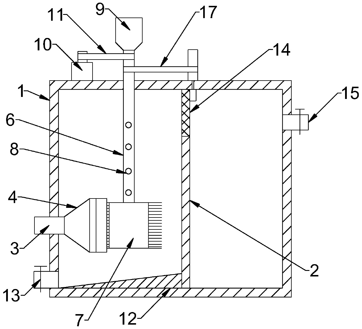
[0022] see Figure 1~2 , in an embodiment of the present invention, a water treatment device for chemically polluted waters includes a housing 1, on which a water inlet structure and a reagent adding structure for treating chemical pollution are communicated, and the housing 1 1. A precipitation treatment chamber and a water outlet chamber are separated by a partition 2. The upper part of the partition 2 is inlaid with a fine mesh plate 14 for connecting the precipitation treatment chamber and the water outlet chamber. The reagent adding structure is driven to rotate by a driving motor 10 and is connected with Water intake structure activity coordination.

[0023] The driving motor 10 is a servo motor, which is continuously forward and reverse after starting.

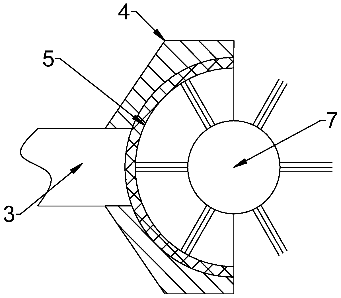
[0024] The water inlet structure penetrates into the housing 1 through one side of the precipitation treatment chamber, the reagent addition structure extends through the top of the precipitation treatment chamber and ...

Embodiment 2

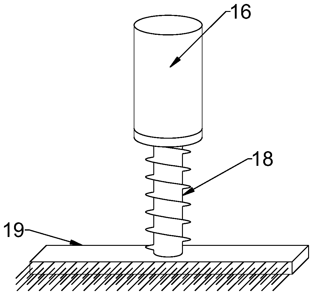
[0029] see figure 1 and 3 , in the embodiment of the present invention, a water treatment device for chemically polluted waters, on the basis of embodiment 1, a cleaning mechanism for removing dirt on the surface of the fine mesh plate 14 is connected above the side of the water outlet chamber, The cleaning mechanism is connected to the rotating pipeline 6 for transmission.

[0030] The cleaning mechanism includes a rotating sleeve 16 rotatably arranged on the housing 1 and a lifting rod 18 movably fitted at the lower end of the rotating sleeve 16. The rotating sleeve 16 is rotatably connected to the upper end of the housing 1 through a sealed bearing, and the The lower end of the rotating sleeve 16 communicates with the water outlet cavity, and the upper peripheral part of the rotating sleeve 16 and the upper peripheral part of the rotating pipe 6 are connected and driven through the second transmission belt 17; the lifting rod 18 is movably connected to the rotating sleeve ...


PUM


Abstract

The invention discloses a water treatment apparatus for chemically polluted water areas. The water treatment apparatus comprises a shell, which is communicated to a water inlet structure and a reagentadding structure for treating chemical pollution, wherein the shell is separated into a precipitation treatment chamber and a water outlet chamber by a separation plate, a fine mesh plate for communicating the precipitation treatment chamber and the water outlet chamber is embedded on the upper portion of the separation plate, the reagent adding structure is driven to rotate by a driving motor, and is movably matched with the water inlet structure, and a cleaning mechanism for clearing scale from the surface of the fine mesh plate is connected above one side of the water outlet chamber, and forms connection transmission with a rotation pipeline. According to the present invention, the floc can be intercepted by the coarse mesh plate, such that the condition that the floc enters the apparatus to affect the water treatment can be avoided; the cleaning head is driven to rotate by the rotation pipeline, such that the impurities can be avoided from being attached to the surface of the coarse mesh plate so as to prolong the continuous use time of the apparatus; and the bush rotates to synchronously perform forward rotation and reverse rotation so as to drive the brush rod to clean the surface of the fine mesh plate.

Description

technical field [0001] The invention relates to the technical field of water conservancy, in particular to a water treatment device for chemically polluted waters. Background technique [0002] Water conservancy projects are projects built to control and allocate natural surface water and groundwater to achieve the purpose of eliminating harm and rejuvenating profits. Only by building water conservancy projects can we control water flow, prevent floods, and regulate and distribute water to meet the needs of people's life and production for water resources. Some waters or water bodies in local areas are polluted during the regulation process, ordinary impurity filtration cannot deal with water body problems well, and if the water bodies in this area are directly deployed, the pollution will affect other water areas. [0003] In the prior art, adsorbents or chemicals are generally used to treat chemically polluted water bodies. Adsorbents are suitable for the treatment of a s...

Claims


Application Information

Patent Timeline
Patent Type & Authority Applications(China)
IPC IPC(8): C02F9/04
CPCC02F1/001C02F1/52C02F2303/14
Inventor 信元利
Owner 信元利
Why Eureka
Try Eureka