
Frost-free heat pump system device for reverse-flow reverse-osmosis regeneration and method

A heat pump system and reverse osmosis technology, applied in the field of air conditioning and refrigeration, can solve the problems of difficult to achieve stable coordination between stages, reduce actual operating pressure, and low regeneration efficiency, and achieve the effects of convenient upgrading, avoiding operating pressure, and small equipment volume

Active Publication Date: 2019-09-03
ZHEJIANG SCI-TECH UNIV
View PDF8 Cites 0 Cited by
  • Summary
  • Abstract
  • Description
  • Claims
  • Application Information

AI Technical Summary

Problems solved by technology

Atmospheric pressure regeneration uses packed tower regeneration. This method is simple, but the regeneration efficiency is low; when vacuum regeneration is used, the regeneration system needs to maintain a high vacuum state during operation, which poses high demands on equipment manufacturing and management. Require
[0005] Membrane methods can also be used to regenerate antifreeze, such as membrane distillation and reverse osmosis. Reverse osmosis does not involve a phase change process, which is more convenient in application. However, reverse osmosis is usually aimed at low-concentration solutions. When the concentration of antifreeze is high, the The operating pressure of reverse osmosis needs to be at least 10Mpa, causing great practical difficulties
In order to reduce the operating pressure of reverse osmosis, the patent No. "ZL201310013902.4" proposes a multi-stage reverse osmosis antifreeze regeneration system, which overcomes the disadvantage of high operating pressure when single-stage reverse osmosis regenerates antifreeze , realizing the cascade transfer of moisture in the antifreeze
However, the system requires a large number of stages, and it is not easy to achieve stable cooperation between stages during operation.
In addition, the patent application number "ZL201610825112.X" proposes a countercurrent osmosis power device, which uses countercurrent decompression osmosis to achieve a large change in solution concentration and reduce the actual operating pressure, but the system uses Power generation based on concentration difference instead of antifreeze concentration, which does not belong to the category of reverse osmosis technology

Method used


Image

  • Frost-free heat pump system device for reverse-flow reverse-osmosis regeneration and method
  • Frost-free heat pump system device for reverse-flow reverse-osmosis regeneration and method
  • Frost-free heat pump system device for reverse-flow reverse-osmosis regeneration and method

Examples


Embodiment 1

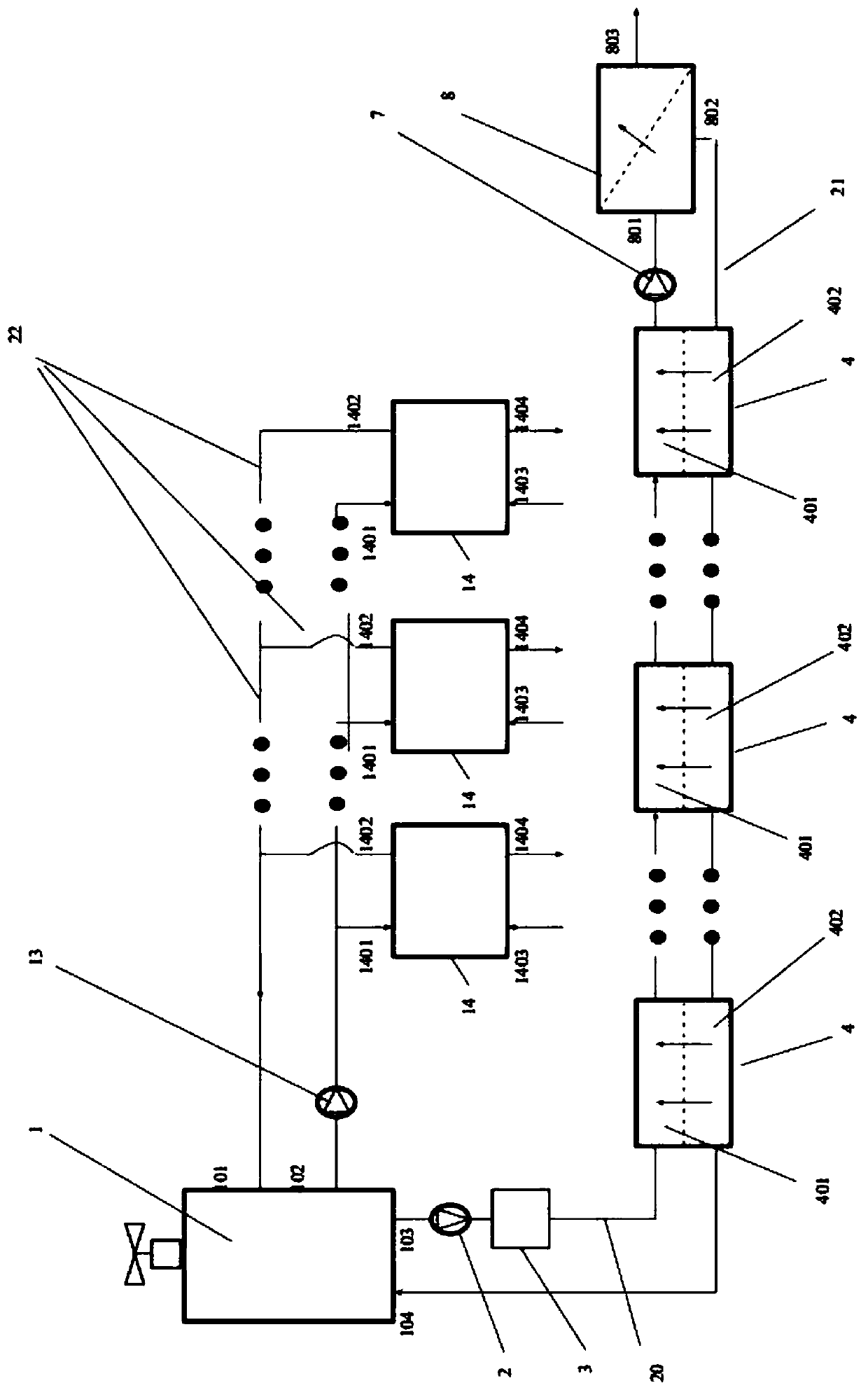
[0074] Embodiment 1, a frost-free heat pump system device type 1 for reverse flow reverse osmosis regeneration, such as figure 1 Shown, including heat pump subsystem I and antifreeze regeneration subsystem II.

[0075] Heat pump subsystem I, the main component for external heating or cooling. It consists of a heat source tower 1, a circulating working medium pump 13, a heat pump host 14 connected in parallel in one or more stages, and a circulating working medium pipeline 22. The circulating working medium pipeline 22 starts from the circulating working medium outlet A102 of the heat source tower 1, and after connecting the circulating working medium pump 13, it is divided into several roads connected in parallel to the circulating working medium inlet B1401 of the heat pump host 14 at each level, and then from the circulating working medium inlet B1401 of the heat pump host 14. After the working medium outlet A1402 comes out, it is connected in parallel to the circulating wo...

Embodiment 2

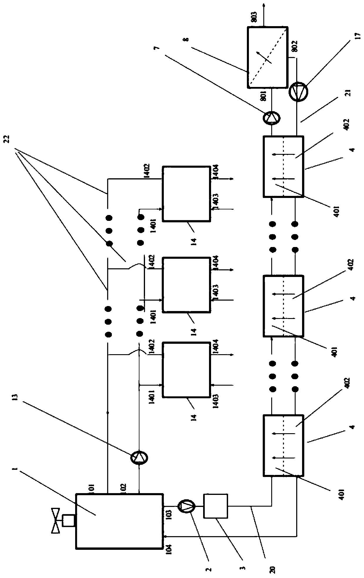
[0091] Embodiment 2, a frost-free heat pump system device type 2 for reverse flow reverse osmosis regeneration, such as figure 2 Shown, including heat pump subsystem I and antifreeze regeneration subsystem II.

[0092] The circulating working fluid and operating mode of the system are the same as in Embodiment 1.

[0093] The structure of heat pump subsystem 1 is the same as that of embodiment 1.

[0094] The structural difference between the antifreeze regeneration subsystem II and the embodiment 1 is: on the basic structure of the antifreeze regeneration subsystem II of the embodiment 1, a device is added between the solution reverse osmosis device 8 and the solution reverse osmosis device 4: reverse osmosis Permeator booster pump 17. That is, the connection of the light-side solution pipeline 20 remains unchanged, and the concentrated-side solution pipeline 21 starts from the solution outlet 802 of the solution reverse osmosis device 8, connects the reverse osmosis boost...

Embodiment 3

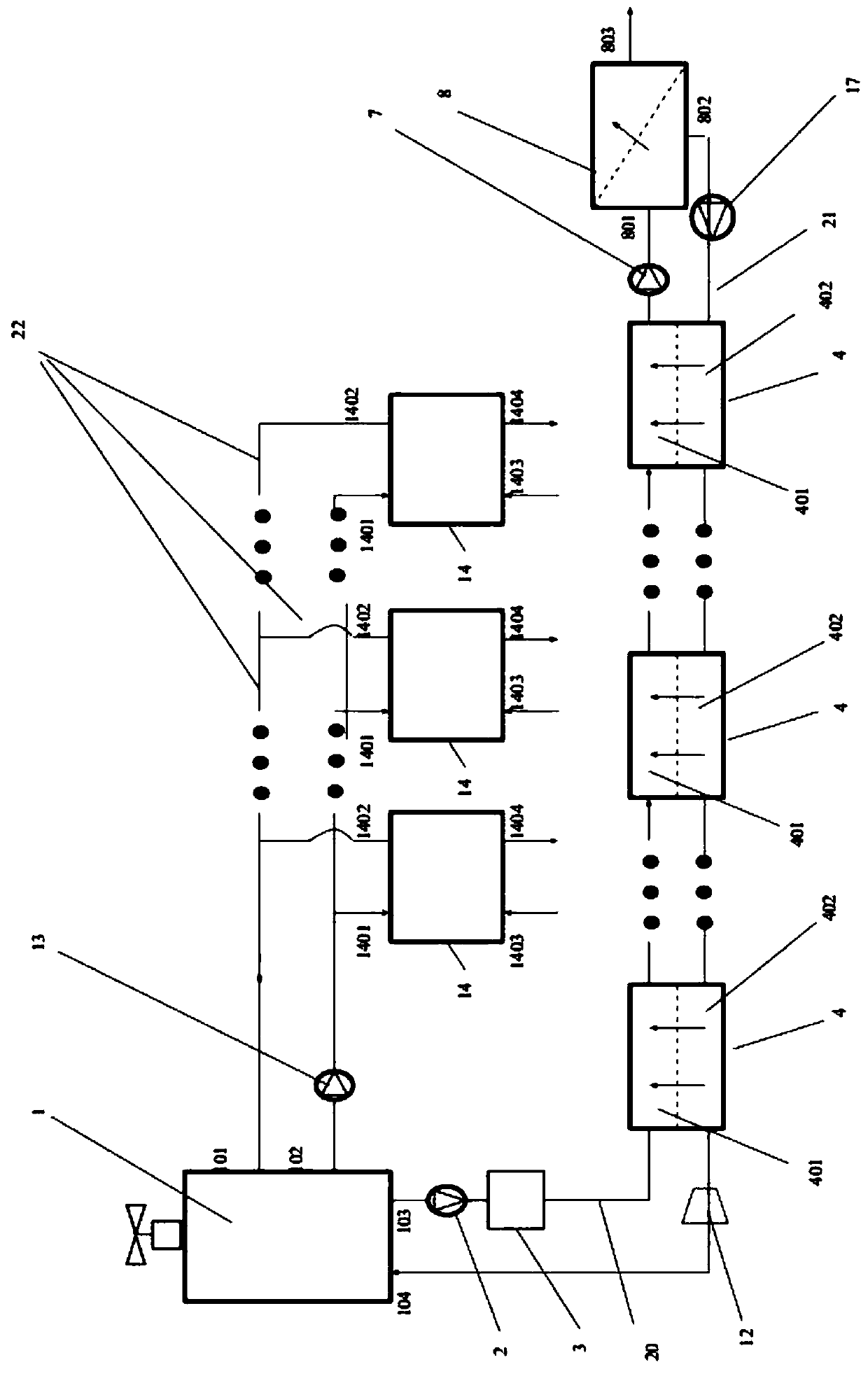
[0105] Embodiment 3, a frost-free heat pump system device type three for reverse flow reverse osmosis regeneration, such as image 3 Shown, including heat pump subsystem I and antifreeze regeneration subsystem II.

[0106] The circulating working fluid and operating mode of the system are the same as in Embodiment 1.

[0107] The structure of heat pump subsystem 1 is the same as that of embodiment 1.

[0108] The structural difference between the antifreeze regeneration subsystem II and embodiment 2 is: on the basic structure of the antifreeze regeneration subsystem II of embodiment 2, a device is added between the first solution reverse osmosis device 4 and the heat source tower 1: the first Level solution reverse osmosis energy recovery device 12. That is, the connection of the light-side solution pipeline 20 remains unchanged, and the concentrated-side solution pipeline 21 starts from the solution outlet 802 of the solution reverse osmosis device 8, connects the reverse o...


PUM


Abstract

The invention discloses a frost-free heat pump system device for reverse-flow reverse-osmosis regeneration. The device comprises a heat pump subsystem (I) and an anti-freezing solution regeneration subsystem (II); the heat pump subsystem (I) is composed of a heat source tower (1), a circulation working medium pump (13), one or more levels of heat pump main units (14) in parallel connection and a circulation working medium pipe (22); the anti-freezing solution regeneration subsystem (II) is composed of an anti-freezing solution circulation pump (2), a filter (3), one or N levels of solution reverse-osmosis devices (4) in parallel connection, a high-pressure pump (7), a pure water reverse-osmosis device (8), a light-side solution pipe (20) and a strong-side solution pipe (21). The inventionfurther a method for heat supply or refrigeration on a frost-free heat pump for the reverse-flow reverse-osmosis regeneration through the device. According to the device, the working efficiency and feasibility of an existing frost-free heat pump can be further improved.

Description

technical field [0001] The invention relates to the field of air-conditioning and refrigeration technology, in particular to a countercurrent reverse osmosis regeneration frost-free heat pump system device and a method thereof. Background technique [0002] Traditional air source heat pumps have serious frosting problems in winter, especially in the low-temperature and high-humidity Yangtze River Basin. This phenomenon causes the host to frequently interrupt the normal heating operation and enter the defrosting mode, which not only affects the normal heating but also reduces The energy efficiency of the whole machine is improved. [0003] In order to solve this problem, the industry has proposed two technical routes for the frost-free operation of air source pumps. One is to use a dehumidifier to dehumidify the humid air first, reduce the dew point temperature of the humid air, and prevent the humid air from frosting on the surface of the heat exchanger. , but this method r...

Claims


Application Information

Patent Timeline
IPC IPC(8): F25B30/04
CPCF25B30/04
Inventor 王厉骆菁菁
Owner ZHEJIANG SCI-TECH UNIV
Learn More