Antenna welding positioning tool and welding method thereof

A technology for welding positioning tooling and welding methods, applied in welding equipment, high-frequency current welding equipment, manufacturing tools, etc., can solve the problems of workers' hand fatigue, poor welding, repeated welding actions, etc., and achieve simple and reasonable, low manufacturing cost, The effect of reducing fatigue

Active Publication Date: 2019-09-06
NANJING UNIV OF SCI & TECH
View PDF8 Cites 0 Cited by
  • Summary
  • Abstract
  • Description
  • Claims
  • Application Information

AI Technical Summary

Problems solved by technology

[0003] The purpose of the present invention is to provide an antenna welding positioning tool and its welding m

Method used


Image

  • Antenna welding positioning tool and welding method thereof
  • Antenna welding positioning tool and welding method thereof
  • Antenna welding positioning tool and welding method thereof

Examples


Example Embodiment

[0023] The present invention will be described in further detail below in conjunction with the accompanying drawings.
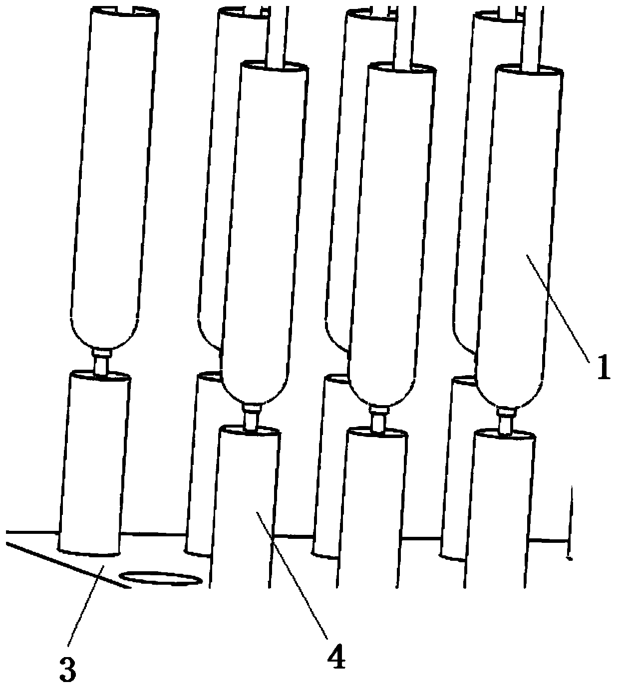
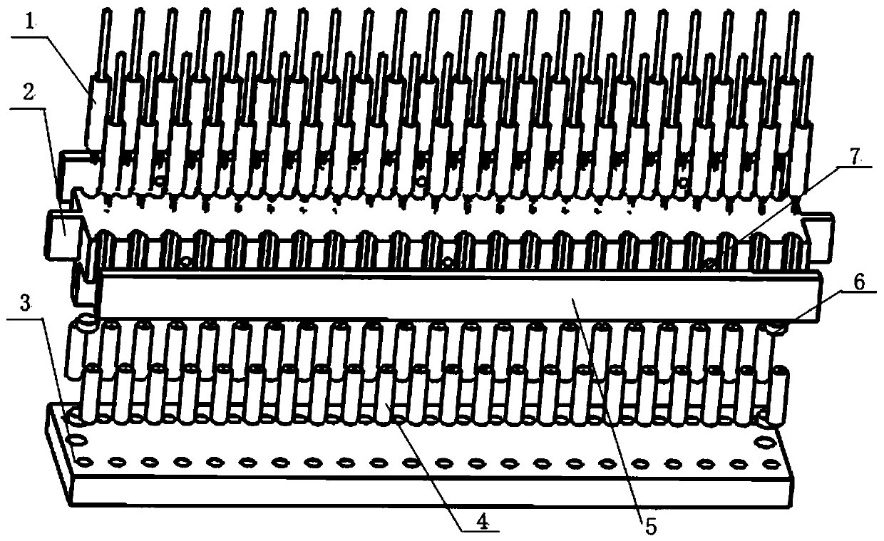
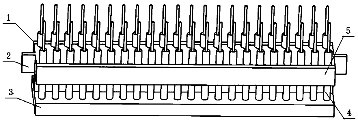
[0024] Combine Figure 2 to Figure 7 , An antenna welding positioning tool, including a solid frame 2, a lower jig plate 3, a baffle 5, a 6mm diameter magnet 6 and a 3mm diameter magnet 7; the lower jig plate 3 is provided with 2 rows of holes for the zinc alloy pillars 4 9 Place the zinc alloy column 4 and 2 holes 8 for placing the 6mm diameter magnet 6; the solid frame 2 is provided with 2 rows of copper pipe grooves 10 for placing the copper pipeline components 1, and 3 holes on each side 11 Place the 3mm diameter magnet 7 and fix it by the baffle 5 to ensure that the copper pipe material assembly 1 will not fall; finally, the solid frame 2 is placed on the bottom surface of the 2 6mm diameter holes to place the 6mm diameter magnet 6 and the lower jig plate The iron absorption stone in the hole position 8 of 3 is connected, and the whole tooling is combined ...


PUM


Abstract

The invention discloses an antenna welding positioning tool and a welding method thereof. The tool comprises a fixed frame, a lower jig plate and a baffle. At least one row of holes are formed in thelower jig plate, and are used for containing zinc alloy columns. Grooves for containing copper pipe wire assemblies are formed in at least one side face of the fixed frame. When the fixed frame is placed over the lower jig plate, the grooves and the holes are used in cooperation one to one, the fixed frame and the lower jig plate are detachably connected, the baffle can be detachably fixed to theside face of the fixed frame, the zinc alloy columns are placed into the holes in the lower jig plate, the copper pipe wire assemblies are fixedly arranged in the grooves in the fixed frame, and thenwelding can be carried out in a high-temperature welding manner. The antenna welding positioning tool has the advantages of being simple and reasonable in structural design, convenient to use, low inmaking cost, high in welding quality, lower in fatigue level of workers and the like.

Description

technical field [0001] The invention belongs to the technical field of antennas, and in particular relates to an antenna welding positioning tool and a welding method thereof. Background technique [0002] In the existing antenna assembly line, the front end of the copper pipe wire 1 is a conductor, and the end of the exposed part of the conductor is an insulating layer. The top part of the zinc alloy column 4 has a blind hole for the conductor to be inserted into. When the zinc alloy column is welded, the conductor is inserted into the blind hole. Welding, during the welding process, the conductor continues to enter the blind hole until the insulation layer of the copper pipe and wire just touches the upper surface of the zinc alloy column, and then the welding is stopped. The welded state is as follows: figure 1 As shown, in the existing welding, the employee takes down the jig plate 3 with his left hand, and takes a handful of copper pipe and wire components with his righ...

Claims


Application Information

Patent Timeline
IPC IPC(8): B23K13/00
CPCB23K13/00
Inventor 林泽宁童一飞盛广瑞
Owner NANJING UNIV OF SCI & TECH
Why Eureka
Try Eureka