Foundation pit cushion layer and manufacture system thereof
A technology for manufacturing systems and cushions, applied in infrastructure engineering, measuring devices, instruments, etc., to achieve the effects of good water resistance, convenient operation and high bending resistance
- Summary
- Abstract
- Description
- Claims
- Application Information
AI Technical Summary
Problems solved by technology
Method used
Image
Examples
Embodiment 1
[0041] Such as figure 1 As shown, a foundation pit cushion layer of this embodiment includes a template 300. The template 300 includes an upper template layer 310, a middle template layer 320, and a lower template layer 330 that are sequentially connected by pouring. The middle template layer 320 is integrally formed and The upper surface and the lower surface of the middle template layer 320 are respectively provided with extension sections extending outward and spaced apart, so that the upper surface of the middle template layer 320 and the upper template layer 310, the lower surface of the middle template layer 320 and the lower template The layers 330 each have a gap cavity 340 surrounded by extension sections.
[0042] In this embodiment, the upper surface and the lower surface of the template 300 are provided with waterproof layers, and the gap cavity 340 in the template 300 includes a large gap cavity assembly and a small gap cavity assembly. The large gap cavity assembly c...
Embodiment 2
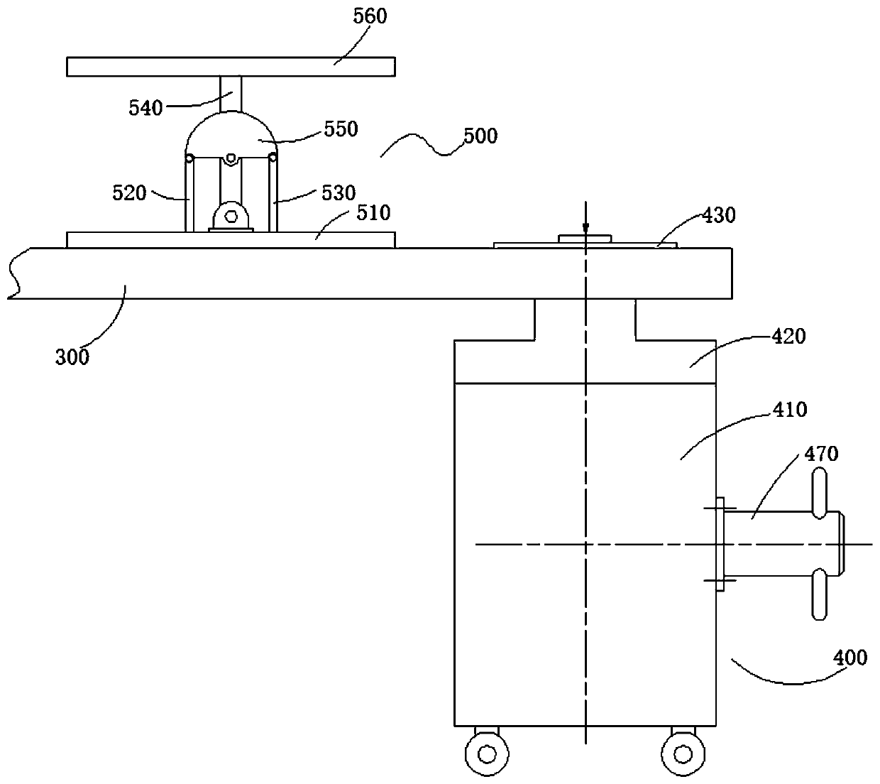
[0045] The manufacturing system of a foundation pit cushion layer of this embodiment is used to manufacture the template 300 in embodiment 1. The manufacturing system is as figure 2 , image 3 , Figure 4 As shown, it includes a fixing mechanism 400 for fixing the template 300 and a leveling mechanism 500 for leveling the template 300. The fixing mechanism 400 includes a main body 410, a guide post 440, a drive shaft 450 and a pressing plate 430, and the guide post 440 is arranged at In the main body 410, the top end of the guide post 440 extends out of the main body 410 and is provided with a pressing plate 430, the template 300 is sleeved on the guide post 440 through a mounting hole, and is located below the pressing plate 430, and the drive shaft 450 is used to drive the guide post 440 to move up and down; As a result, the pressing plate 430 is driven to press the template 300 downwards or detach from the template 300 upwards, so as to achieve compression and reinforcement o...
Embodiment 3
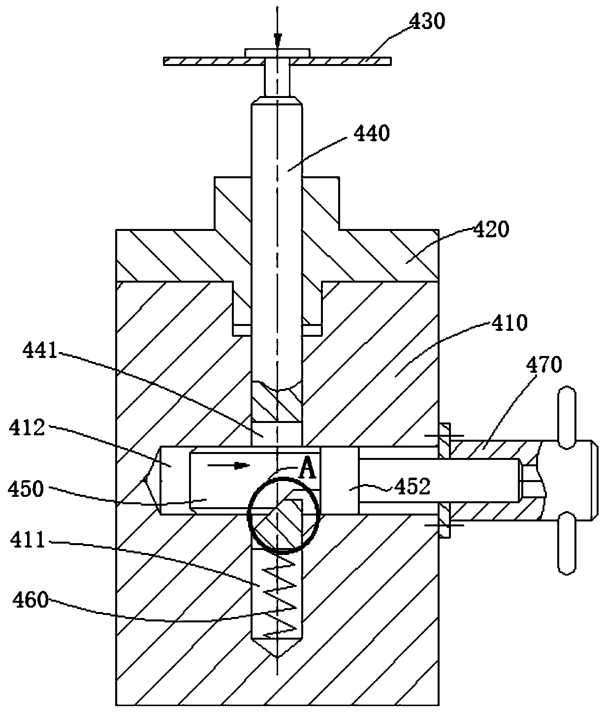
[0051] The manufacturing system of a foundation pit cushion in this embodiment is basically the same as the above embodiment, and further, such as image 3 with Figure 4 As shown, the main body 410 in this embodiment is provided with a longitudinal hole 411 for placing the guide post 440 and a transverse hole 412 for placing the drive shaft 450. The longitudinal hole 411 and the transverse hole 412 intersect perpendicularly; the lower part of the guide post 440 is provided with The through hole 441 in the column through which the drive shaft 450 passes. The diameter of the through hole 441 in the column is larger than the diameter of the drive shaft 450. The lower surface of the inner wall of the through hole 441 in the column is a lower wedge surface 442, and the lower surface of the drive shaft 450 is cut A mating inclined surface 451 adapted to the lower wedge surface 442 is formed; a telescopic elastic member 460 (such as a telescopic spring) is arranged in the cavity formed...
PUM
 Abstract
Description
Claims
Application Information
 - R&D
- Intellectual Property
- Life Sciences
- Materials
- Tech Scout
- Unparalleled Data Quality
- Higher Quality Content
- 60% Fewer Hallucinations
Browse by: Latest US Patents, China's latest patents, Technical Efficacy Thesaurus, Application Domain, Technology Topic, Popular Technical Reports.
© 2025 PatSnap. All rights reserved.Legal|Privacy policy|Modern Slavery Act Transparency Statement|Sitemap|About US| Contact US: help@patsnap.com


