
Method and device for joint reinforcement of underground diaphragm wall

An underground diaphragm wall and fixing frame technology, which is applied to sheet pile walls, underwater structures, buildings, etc., can solve the problems of high cost, failure, water leakage of the enclosure structure, quicksand, etc., and achieve low cost and prevention of enclosure structure The effect of water leakage problems

Active Publication Date: 2022-07-08
SHANGHAI JIANKE ENG CONSULTING
View PDF7 Cites 0 Cited by
  • Summary
  • Abstract
  • Description
  • Claims
  • Application Information

AI Technical Summary

Problems solved by technology

In addition, the cost of using these plugging methods is high
[0003] For the underground diaphragm wall adopting milling joints and locking pipe joints, mud is likely to be trapped in the joints between the first and second underground diaphragm walls, which will lead to water leakage of the enclosure structure during foundation pit excavation. Quicksand, especially in pressurized water formations, can cause foundation pit leakage accidents
When the foundation pit is excavated at a depth of 20m or above and is affected by confined water, this plugging method may fail, which may lead to a burst of confined water or a piping accident, resulting in serious economic losses and damage to the surrounding environment

Method used


Image

  • Method and device for joint reinforcement of underground diaphragm wall
  • Method and device for joint reinforcement of underground diaphragm wall
  • Method and device for joint reinforcement of underground diaphragm wall

Examples


Embodiment Construction

[0030] The present invention will be further described below in conjunction with the accompanying drawings and embodiments

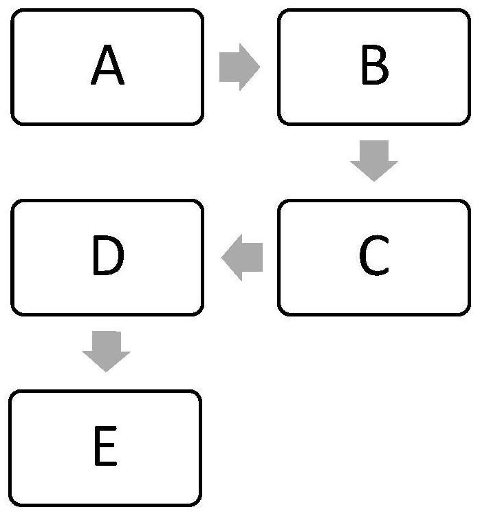
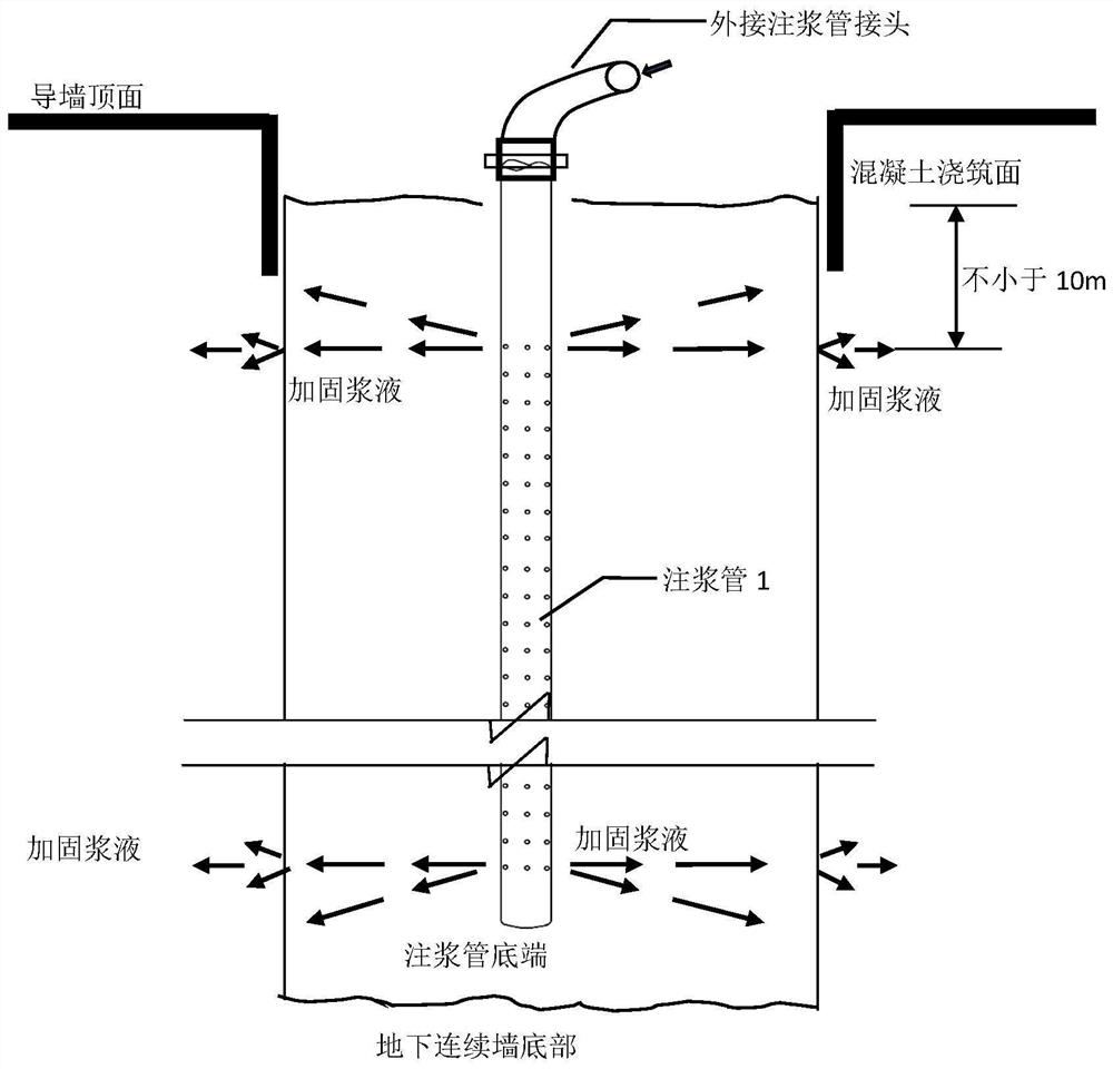
[0031] A joint reinforcement method of an underground continuous wall of the present invention (as attached figure 1 , 2 shown), including steps:

[0032] A. At the end of the trough formation of the underground diaphragm wall of the rear width, the verticality of the trough is detected by ultrasonic wave, the joints are brushed, and the steel cage of the underground diaphragm wall of the running width is completed after the hoisting is completed.

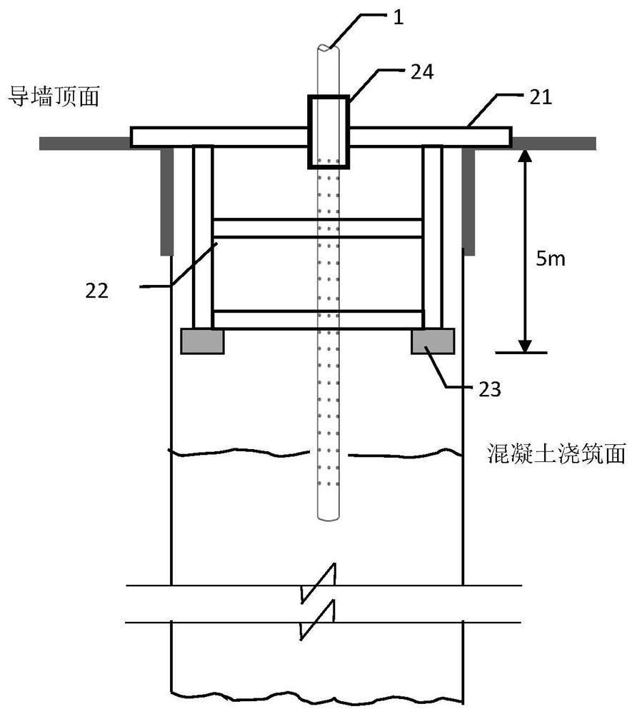
[0033] B. Place the joint grouting pipe fixing frame.

[0034] C. Lay down the grouting pipe, keep the grouting pipe close to the joint wall of the leading underground diaphragm wall by adjusting the regulator on the grouting pipe fixing frame, and adjust the verticality of the grouting pipe inside and outside the foundation pit; the bottom of the grouting pipe should be 1m to 3m above the bottom of the un...


PUM


Abstract

The invention relates to a method and a device for reinforcing a joint of an underground continuous wall, and relates to the technical field of leakage plugging of the underground continuous wall. The steps of the method include: (1) forming a groove in the underground diaphragm wall, performing ultrasonic detection on the verticality of the groove, performing joint brushing, and hoisting to complete the underground diaphragm wall reinforcement cage; (ii) placing the joint grouting pipe fixing frame; Slurry pipe...; IV lowering the concrete pouring conduit...; V The concrete strength of the diaphragm wall reaches 50% of the design strength and above, and the concrete pouring time is not less than 5 days, and the joints of the diaphragm wall are reinforced through the grouting pipe Slurry injection…. The invention solves the problems of mud inclusion, concrete segregation and non-compactness in the joints of the underground continuous wall, effectively prevents the problems of water leakage and quicksand of the underground continuous wall during the excavation of the foundation pit, and proposes a corresponding device. Compared with the underground diaphragm wall plugging method in the process of foundation pit excavation, it has the advantages of safety, low risk, low cost, high efficiency and high quality.

Description

technical field [0001] The invention relates to the technical field of leakage plugging of underground continuous walls, in particular to a method and a device for strengthening joints of underground continuous walls. Background technique [0002] With the development and utilization of urban underground space in my country, the depth of underground engineering construction is getting deeper and deeper. For cities in coastal or riverside soft soil areas, foundation pit engineering is an important part of underground engineering, and the enclosure structure is the premise to ensure the safety of foundation pit engineering. Affected by the constraints of the surrounding conditions of the city and the complexity of geological conditions, the underground diaphragm wall is used as the enclosure structure in the deep foundation pit project in the soft soil area. During the excavation of the foundation pit, when there is water leakage and quicksand in the foundation pit, the leaka...

Claims


Application Information

Patent Timeline
Patent Type & Authority Patents(China)
IPC IPC(8): E02D29/16E02D19/18E02D5/18
CPCE02D29/16E02D19/18E02D5/18E02D2250/0023
Inventor 蔡来炳周红波王志德周翠
Owner SHANGHAI JIANKE ENG CONSULTING
Learn More