Double-water stop structure for concrete expansion joint and manufacturing and construction method for double-water stop structure

A technology of concrete and expansion joints, which is applied in underwater structures, infrastructure engineering, earthwork drilling and mining, etc. It can solve the problems of irregular deformation of concrete tanks, prolonging the construction period, and difficult cleaning, so as to save installation procedures, reduce construction period, The effect of preventing cross-sectional interface misalignment

Inactive Publication Date: 2014-05-28
SHANDONG JIAOTONG UNIV
View PDF5 Cites 24 Cited by
  • Summary
  • Abstract
  • Description
  • Claims
  • Application Information

AI Technical Summary

Problems solved by technology

[0002] In existing concrete structures, such as retaining dams, reservoirs, subways, culverts, sluices, tunnels and other underground projects, due to the inability to pour continuously or the deformation of the foundation settlement (earthquake), or the concrete caused by temperature changes Expansion joints and deformation joints should be reserved during pouring due to thermal expansion and contraction of components, and anti-leakage measures should be taken for these gaps to prevent external water or groundwater from leaking into the structural space. A concrete groove is set between the stage concrete and the second stage concrete, and soft asphalt and copper sheets or rubber waterstops are arranged in the groove. However, this method requires prefabricated concrete grooves. The 3 sides of the groove are chiseled, which will prolong the construction period and increase labor. At the same time, since the length (height) of each concrete groove is generally only 50-100cm, the expansion gap must be composed of multiple concrete grooves, so there will be multiple Horizontal gaps and irregular deformation of multiple concrete grooves will cause run-off of soft asphalt poured in the subsequent sequence, and it is difficult to clean up

Method used


Image

  • Double-water stop structure for concrete expansion joint and manufacturing and construction method for double-water stop structure
  • Double-water stop structure for concrete expansion joint and manufacturing and construction method for double-water stop structure
  • Double-water stop structure for concrete expansion joint and manufacturing and construction method for double-water stop structure

Examples


Embodiment

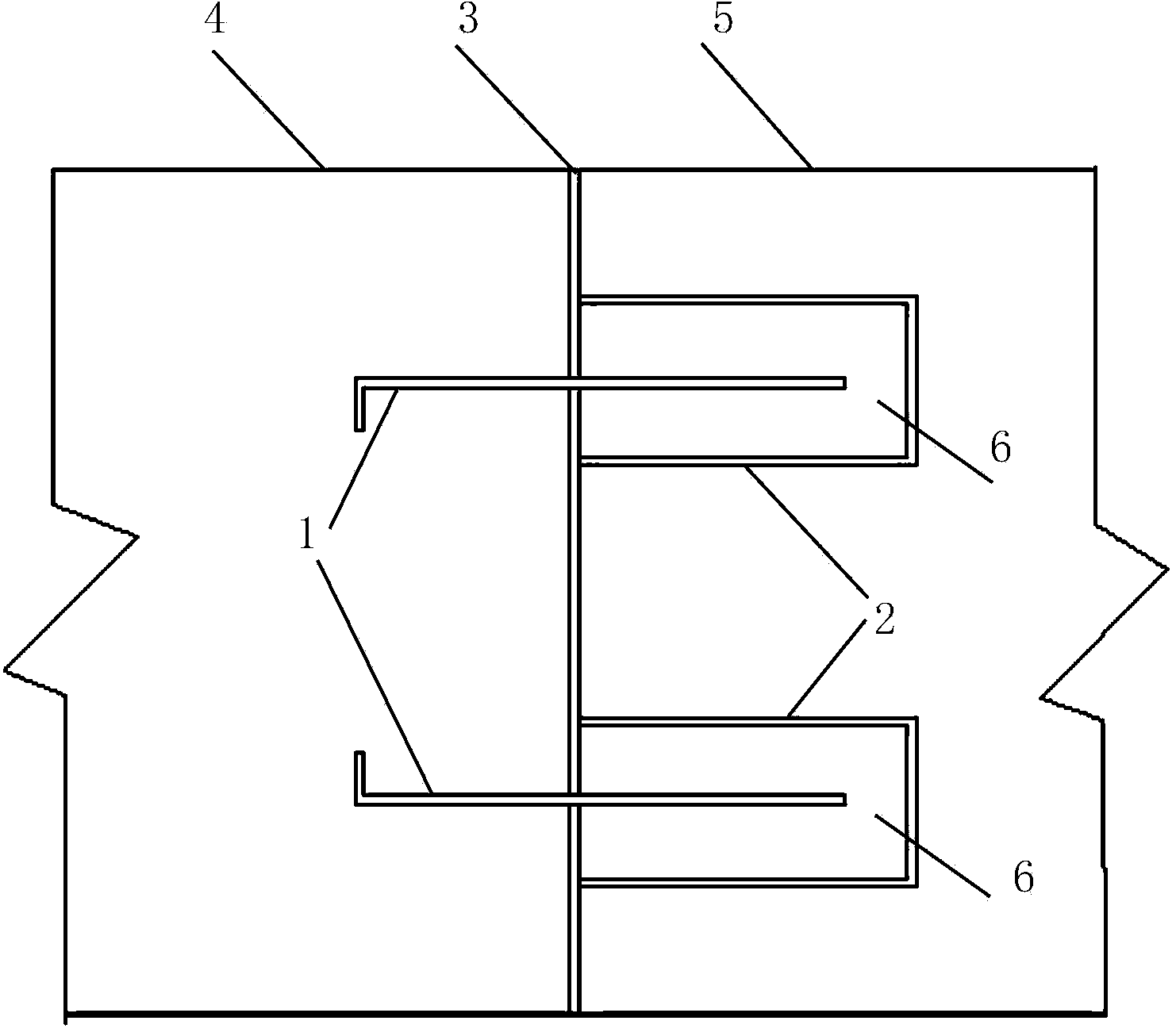
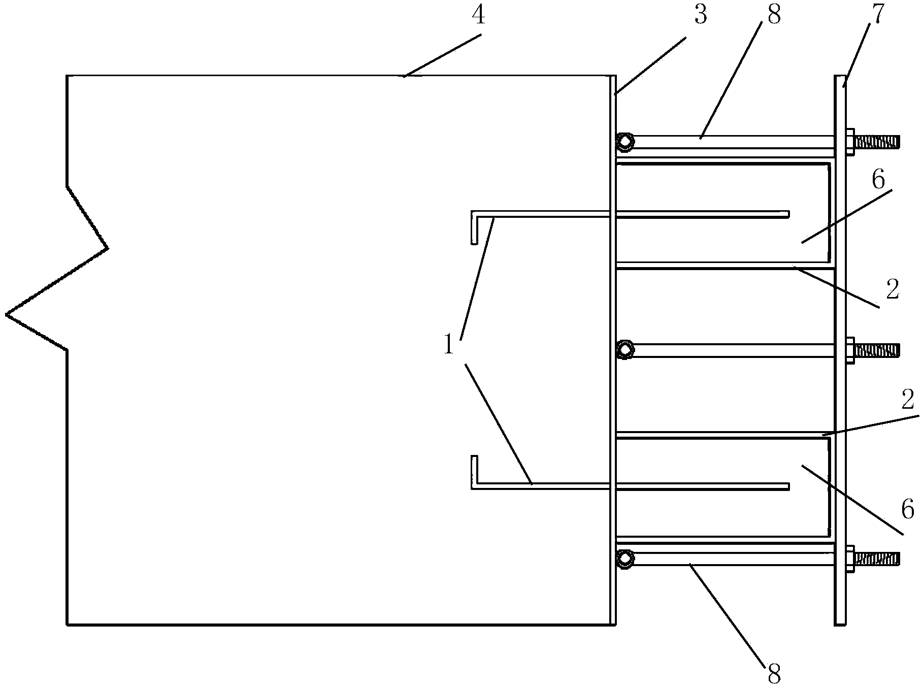
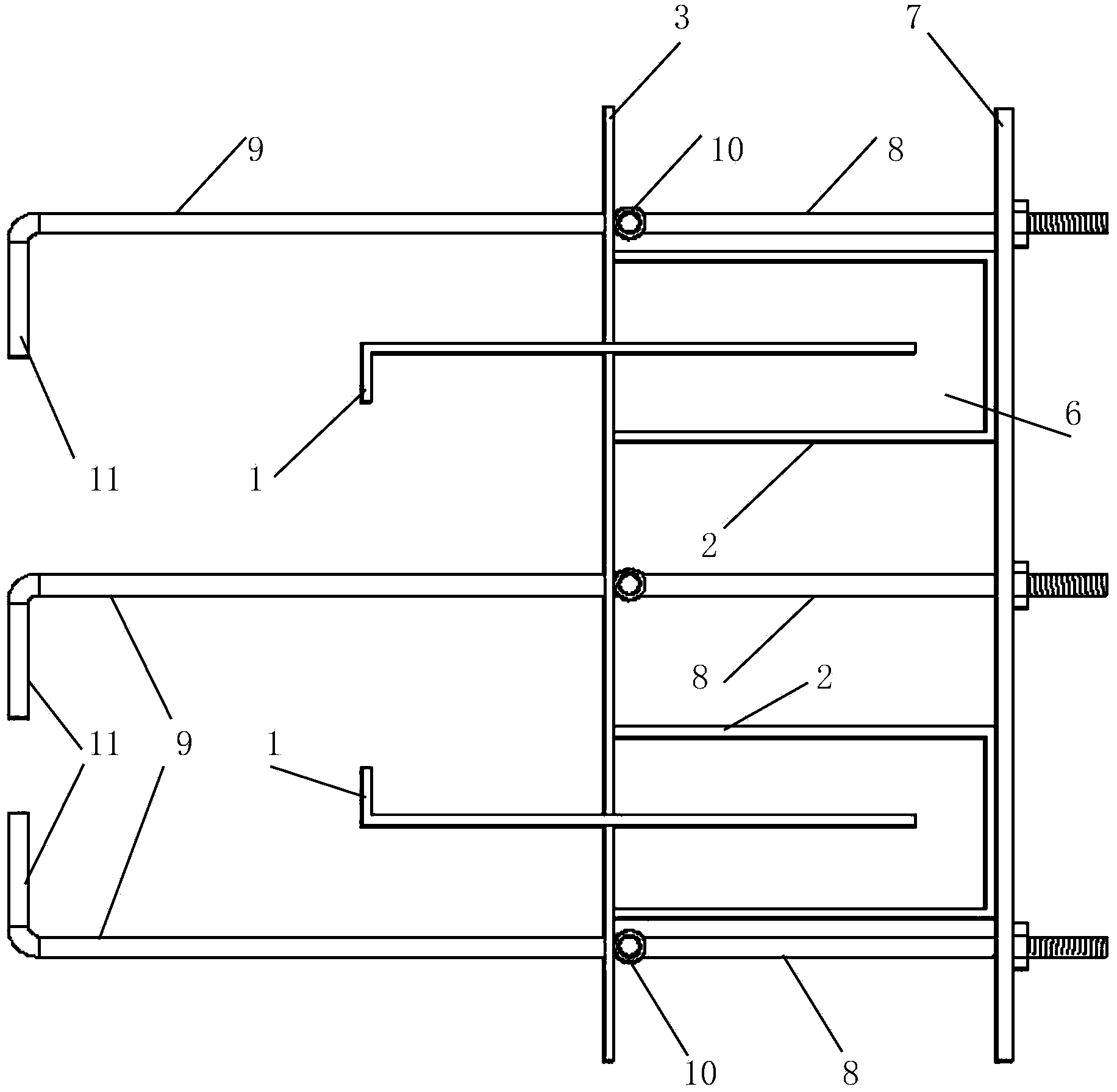
[0044] Embodiment, referring to the accompanying drawings: a concrete expansion joint double water-stop structure, including a deformation piece 1, a channel steel 2, two deformation pieces 1 are provided on the concrete section, and the two deformation pieces 1 are vertically arranged at a predetermined distance , half of which is pre-embedded in the first-stage concrete 4, and the other half protrudes from the concrete section and is respectively arranged in the corresponding channel steel 2, and the channel steel 2 is provided with asphalt 6; the channel steel 2 Linoleum 3 is provided on the opening surface and the section of the first-stage concrete 4 .

[0045]Further, the deformable sheet 1 is in the form of a rectangular plate with a width of 30-60 cm and a length equal to the height of the concrete section. The side poured into the concrete is bent at 90° with a bending height of 2-5 cm. Two deformable sheets 1 are respectively arranged on The distance between the two ...


PUM


Abstract

The invention relates to an underground (underwater) building waterproof device, in particular to a double-water stop structure for a concrete expansion joint and a manufacturing and construction method for the double-water stop structure. The double-water stop structure comprises two deformation sheets and channel beams. The double-water stop structure is characterized in that a concrete section is provided with the two deformation sheets; the two deformation sheets are longitudinally arranged at a set distance; half of each deformation sheet is embedded in primary concrete, and the other half of each deformation sheet protrudes out of the concrete section, and the other halves of the two deformation sheets are respectively arranged in the corresponding channel beams; asphalt fills each channel beam; an asphaltic felt is arranged on open surfaces of the channel beams and a primary concrete section; exposed fixed parts are removed after the asphalt is cooled, and then, secondary concrete is set. According to the double-water stop structure disclosed by the invention, the water seepage problem caused by differential settlement or faulting of a stratum in hydraulic engineering can be solved; the labor can also be reduced, and the construction period can also be shortened.

Description

technical field [0001] The invention relates to an underground (underwater) building waterproof device, in particular to a concrete expansion joint double water-stop structure and its manufacturing and construction methods. Background technique [0002] In existing concrete structures, such as retaining dams, reservoirs, subways, culverts, sluices, tunnels and other underground projects, due to the inability to pour continuously or the deformation of the foundation settlement (earthquake), or the concrete caused by temperature changes Expansion joints and deformation joints should be reserved during pouring due to thermal expansion and contraction of components, and anti-leakage measures should be taken for these gaps to prevent external water or groundwater from leaking into the structural space. A concrete groove is set between the stage concrete and the second stage concrete, and soft asphalt and copper sheets or rubber waterstops are arranged in the groove. However, this...

Claims


Application Information

Patent Timeline
Patent Type & Authority Applications(China)
IPC IPC(8): E02D31/02E02D29/16E02B3/16E21D11/38
Inventor 张朝利
Owner SHANDONG JIAOTONG UNIV
Why Eureka
Try Eureka