power unit

A power unit and engine technology, applied to engine components, motor vehicles, machines/engines, etc., to achieve the effect of improving cooling efficiency

Active Publication Date: 2022-03-01
HONDA MOTOR CO LTD
View PDF7 Cites 0 Cited by
  • Summary
  • Abstract
  • Description
  • Claims
  • Application Information

AI Technical Summary

Problems solved by technology

Therefore, since the cooling fans are respectively arranged at both ends of the crankshaft, the size of the power unit in the axial direction of the crankshaft is increased.

Method used


Image

  • power unit
  • power unit
  • power unit

Examples


Embodiment Construction

[0061] Hereinafter, an embodiment of the present invention will be described with reference to the drawings. In addition, in the following description, each direction of front-back, up-down, and left-right is the direction seen from the occupant of a two-wheeled motor vehicle.

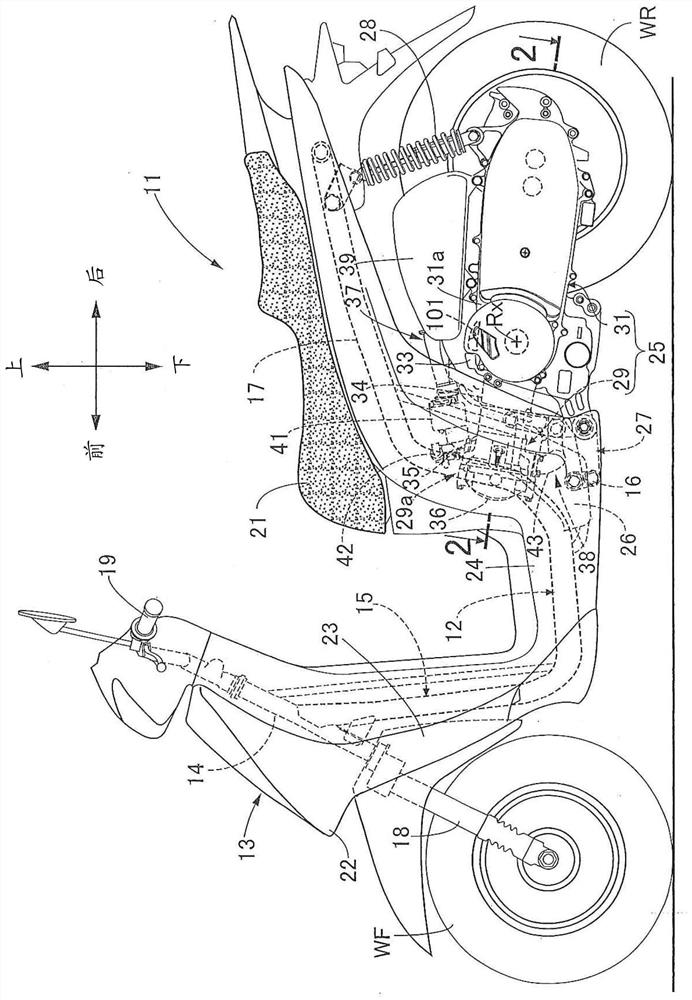
[0062] figure 1 A small two-wheeled vehicle that is one embodiment of a saddle-riding vehicle is schematically shown. The motorcycle 11 has a frame 12 and a body cover 13 attached to the frame 12 . The vehicle frame 12 has a head pipe 14 at its front end, a main frame 15 combined with the head pipe 14 at the front end, a cross pipe 16 combined at the rear of the main frame 15 and extending in the vehicle width direction, and the front end is connected to the cross pipe respectively. Both ends of the pipe 16 are a pair of left and right rear frames 17 extending in the vehicle front-rear direction. A front fork 18 and a bar-shaped steering handle 19 are supported on the head pipe 14 so as to be steera...


PUM


Abstract

The present invention provides a power unit downsized in the axial direction of a crankshaft. The power unit has: a radiator (58), which is arranged at a position opposite to one end of the crankshaft (45) protruding from the first case half (33a), and connected to the water jacket (52b) by piping; a belt type continuously variable transmission , which has a belt (63) wrapped around a drive pulley (59) mounted on a crankshaft (45) protruding from the second case half 33b; transmission box, which is connected to the crankshaft The box (33) is connected to form a transmission chamber (68) for accommodating the belt (63); a cooling fan (97), which is fixed on the crankshaft (45), generates an air flow corresponding to the rotation of the crankshaft (45); the first guide path (99a), which guides the airflow of the cooling fan (97) towards the belt (63) in the transmission chamber (68); the second guide path (99b), which guides the airflow of the cooling fan (97) through the radiator (58) to boot.

Description

technical field [0001] The present invention relates to a power unit (unit swing engine) having a cooling fan fixed to a crankshaft and generating an air flow corresponding to the rotation of the crankshaft. Background technique [0002] Patent Document 1 discloses a power unit including: an internal combustion engine (engine main body), which has a crankcase that supports a crankshaft so that it can rotate freely around a rotation axis; The radiator connected by the water jacket; the belt type continuously variable transmission, which transmits the power of the crankshaft to the driven shaft with a continuously variable speed ratio. [0003] Patent Document 1: (Japanese) Unexamined Patent Application Publication No. 2013-204505 [0004] The power unit described in Patent Document 1 has a cooling fan with one end fixed to the crankshaft that sucks in external air and directs it toward the belt-type continuously variable transmission in response to the rotation of the cranks...

Claims


Application Information

Patent Timeline
Patent Type & Authority Patents(China)
IPC IPC(8): F02F7/00F01P5/06F01P11/10F16H57/04
CPCF02F7/007F01P5/06F01P11/10F16H57/0416F01P2050/16F16H57/035F16H57/0475F16H57/0489B62M7/12
Inventor 富冈裕介西田宪二田中宏幸
Owner HONDA MOTOR CO LTD
Why Eureka
Try Eureka