Sensorless control method for extracting optimal rotor position

A technology of rotor position and control method, applied in the direction of electronic commutation motor control, control system, control generator, etc.

Inactive Publication Date: 2019-09-06
CHINA UNIV OF MINING & TECH
View PDF7 Cites 3 Cited by
  • Summary
  • Abstract
  • Description
  • Claims
  • Application Information

AI Technical Summary

Problems solved by technology

[0009] Purpose of the invention: In view of the above problems, the present invention proposes a position sensorless control method based on the parallel design of phase-locked loop and extended Kalman filter to extract the optimal rotor

Method used


Image

  • Sensorless control method for extracting optimal rotor position
  • Sensorless control method for extracting optimal rotor position
  • Sensorless control method for extracting optimal rotor position

Examples


Embodiment Construction

[0088] The technical solutions of the present invention will be further described below in conjunction with the accompanying drawings and embodiments.

[0089] The technical scheme of the present invention is based on the parallel design of the phase-locked loop and the extended Kalman filter to reduce the amplification of the closed-loop feedback control error, and at the same time, it can obtain the best motor rotor position angle in the full speed range. The control scheme can be divided into for the following steps:

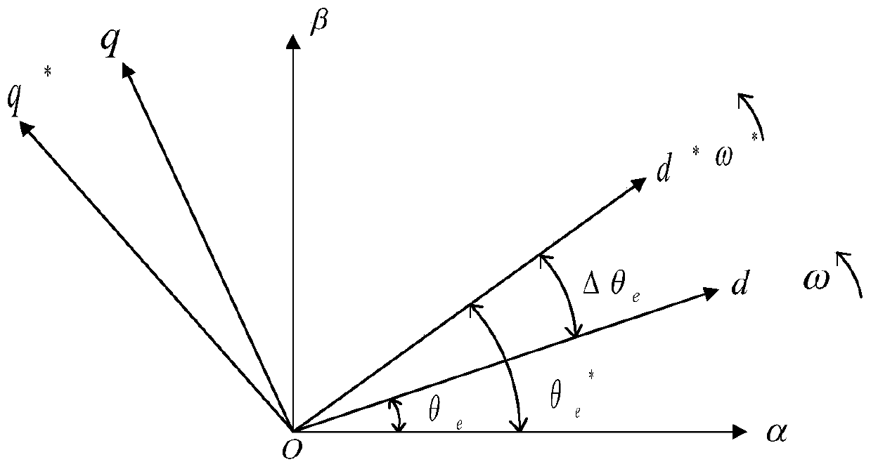
[0090] Step S1: if image 3 shown, using the traditional The vector control method of the reference coordinate system d * -q * Lower reference current command After being processed by the current controller, d * -q * Reference voltage command in the coordinate system In the reference voltage command The high-frequency pulse vibration signal is injected on the basis of the high-frequency voltage to obtain the superimposed signal of the reference vo...


PUM


Abstract

The invention discloses a sensorless control method for extracting the optimal rotor position. The control method comprises the following steps: S1, a high-frequency pulse vibration signal is injectedon the basis of the reference input current by using the conventional vector control method and the superposed signal of the reference input current after the high-frequency voltage is injected is obtained; S2, a motor is driven according to the superposed signal so as to obtain a coupling signal including the rotor position of the motor; S3, the control strategy of the concurrent design is determined according to the coupling signal; and S4, the optimal solution of the rotor position reference value is obtained after the coupling signal is processed by the phase-locked loop and the extendedKalman filter in parallel. The control strategy can effectively solve the transition problem between zero low speed and high speed of the permanent magnet synchronous motor and extract the optimal solution of the rotor position reference value in the full speed range.

Description

technical field [0001] The invention belongs to the field of motor control, in particular to a position sensorless control method for extracting an optimal rotor position. Background technique [0002] Due to high efficiency, high power density and high power factor, permanent magnet synchronous motors are used more and more, such as electric vehicles or wind power generation pitch control. In order to realize a high-performance three-phase permanent magnet synchronous motor control system, it is necessary to obtain the rotor position information of the motor. There are two ways to obtain the rotor position information: [0003] One is to install the position sensor. However, because the position sensor is prone to failure in a harsh environment or is subject to external disturbances, the sensor is damaged, and the maintenance cost increases. [0004] The second is that there is no position sensor, and the rotor position information is estimated from other physical quantit...

Claims


Application Information

Patent Timeline
IPC IPC(8): H02P21/26
CPCH02P21/26H02P2203/03
Inventor 李威田丰杨雪峰王禹桥范孟豹许少毅李敏周红亚杜文龙
Owner CHINA UNIV OF MINING & TECH
Why Eureka
Try Eureka