Eureka AIR delivers breakthrough ideas for toughest innovation challenges, trusted by R&D personnel around the world.

Rotary disc type automatic sand blasting mechanism

A technology of sandblasting machine and turntable type, which is applied in the direction of abrasive jetting machine tools, used abrasive processing devices, abrasives, etc., which can solve the problems of reducing the service life of equipment, reducing production efficiency, and damage to equipment and equipment, so as to prolong the service life , Eliminate safety hazards, avoid the effect of opening and closing equipment

Active Publication Date: 2019-09-10
东莞吉川机械科技股份有限公司
View PDF5 Cites 7 Cited by
  • Summary
  • Abstract
  • Description
  • Claims
  • Application Information

AI Technical Summary

Problems solved by technology

[0003] The traditional sandblasting equipment usually keeps the workpiece still and the spray gun rotates to blast the workpiece, or the spray gun keeps still and the workpiece rotates for sandblasting. For some irregularly shaped workpieces, the sandblasting effect is poor, and there will be local leakage. Resulting in low sandblasting precision and low yield rate of the workpiece;
[0004] Because the high-speed spray beam will harm the human body, there is a great potential safety hazard. When the traditional sandblasting equipment needs to take out or put in the workpiece, it is necessary to stop the entire machine before taking out or putting in the workpiece, so as to protect the operator. The purpose of safety, but this method will reduce production efficiency, and frequent startup and shutdown of equipment will cause great damage to the equipment and reduce the service life of the equipment

Method used


Image

  • Rotary disc type automatic sand blasting mechanism
  • Rotary disc type automatic sand blasting mechanism
  • Rotary disc type automatic sand blasting mechanism

Examples


Embodiment Construction

[0032] In order to facilitate the understanding of those skilled in the art, the present invention will be further described below in conjunction with the embodiments and accompanying drawings, and the contents mentioned in the embodiments are not intended to limit the present invention.

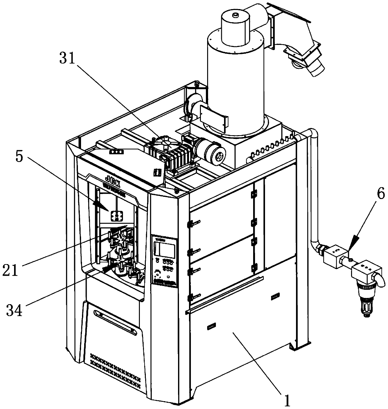
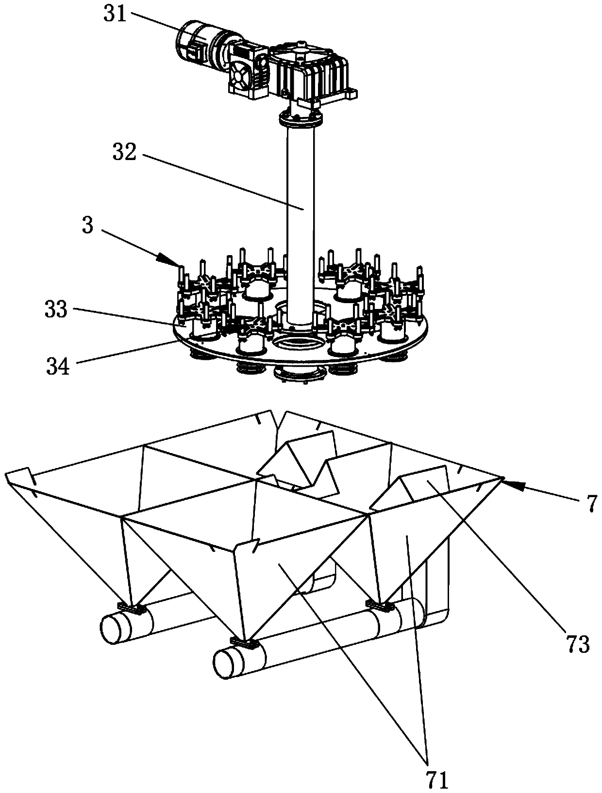
[0033] Such as Figure 1 to Figure 13As shown, a turntable type automatic sandblasting mechanism provided by the present invention includes a sandblasting frame 1, a sandblasting chamber 2 arranged in the sandblasting frame 1, and a sandblasting chamber 2 arranged in the sandblasting frame 1 for carrying workpieces. The turntable carrying device 3, the spray gun device 4 that is movable in the sandblasting room 2 and used for blasting the workpiece carried on the turntable carrying device 3, and the sandblasting device 4 that is set in the sandblasting room 2 and is used to prevent the spray gun device 4 from spraying The isolation device 5 for splashing materials everywhere, and the air pre...


PUM


Abstract

The invention relates to the technical field of sand blasting, in particular to a rotary disc type automatic sand blasting mechanism. The rotary disc type automatic sand blasting mechanism comprises asand blasting machine frame, a sand blasting chamber, a turntable carrying device, a spray gun device, an isolation device and an air pressure supply device, wherein the sand blasting chamber is arranged on the sand blasting machine frame; the turntable carrying device is rotationally arranged on the sand blasting machine frame and is used for bearing a workpiece; the spray gun device is movablyarranged in the sand blasting chamber and is used for carrying out sand blasting treatment on the workpiece which is borne by the turntable carrying device; the isolation device is arranged in the sand blasting chamber; and the air pressure supply device is arranged on the sand blasting machine frame and is used for supplying high-pressure gas to the spray gun device. According to the sand blasting mechanism, the sand blasting treatment precision can be improved, and the yield of the sand-blasted workpiece is improved; and workpieces can be placed onto or taken off the turntable carrying device without stopping the sand blasting mechanism, potential safety hazards are eliminated, the production efficiency is improved, the mechanism is prevented from being frequently started or shut down, the mechanism is protected, and the service life of the mechanism is prolonged.

Description

technical field [0001] The invention relates to the technical field of sand blasting, in particular to a rotary disc type automatic sand blasting mechanism. Background technique [0002] The sandblasting machine uses compressed air as the power to form a high-speed jet beam to spray the spray material (steel sand, quartz sand, corundum, glass sand, resin sand, etc.) change. Due to the impact and cutting effect of the spray on the surface of the workpiece, the surface of the workpiece can obtain a certain degree of cleanliness and different roughness, and the mechanical properties of the surface of the workpiece are improved, so the fatigue resistance of the workpiece is improved, and the surface and coating of the workpiece are increased. The adhesion between layers prolongs the durability of the coating film, and is also conducive to the leveling and decoration of the coating. Sand blasting can remove impurities, variegated colors and oxide layers on the surface of the wor...

Claims


Application Information

Patent Timeline
Patent Type & Authority Applications(China)
IPC IPC(8): B24C3/22B24C7/00B24C9/00
CPCB24C3/22B24C7/0046B24C9/00B24C9/006
Inventor 刘学军杨丙
Owner 东莞吉川机械科技股份有限公司
Why Eureka
Eureka Blog
Learn More