Tie rod joint assembly and its design method
A design method and tie-rod technology, applied in railway car body parts, bogies, transportation and packaging, etc., can solve the problems of short fatigue life, large deflection stiffness, and inability to adjust deflection stiffness, so as to improve fatigue life and improve axle shafts. The effect of increasing stiffness and improving comfort
- Summary
- Abstract
- Description
- Claims
- Application Information
AI Technical Summary
Problems solved by technology
Method used
Image
Examples
Embodiment Construction
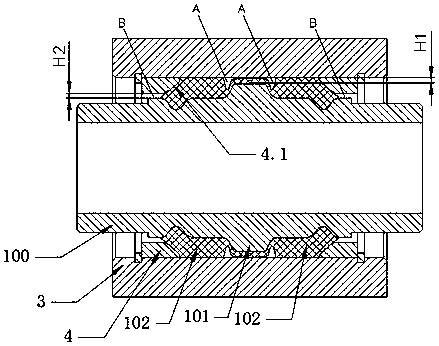
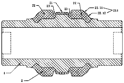
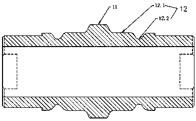
[0037] Combine below Figure 1 to Figure 3 The embodiments of the present invention will be described in detail.
[0038] The tie rod node assembly includes a tie rod 3 and a node 100 pressed into the tie rod 3. The node 100 is composed of a mandrel 1 and a rubber 2 vulcanized and bonded on the mandrel 1. It is characterized in that the node 100 is matched with the tie rod 3. The part is divided into three sections, namely the stop section 101 which is located in the middle and functions as a stopper and the symmetrical section 102 which is mirror-symmetrically arranged on the left and right sides of the stop section. The diameter of the mandrel of the stop section 101 is larger than that of the symmetrical section 102. , and the rubber thickness of the stop segment 101 is smaller than that of the symmetrical segment 102 , the rubber of the stop segment 101 is in a free state, and the rubber of the symmetrical segment 102 is in a pre-compressed state.
[0039] As shown in the...
PUM
 Abstract
Description
Claims
Application Information
 - R&D
- Intellectual Property
- Life Sciences
- Materials
- Tech Scout
- Unparalleled Data Quality
- Higher Quality Content
- 60% Fewer Hallucinations
Browse by: Latest US Patents, China's latest patents, Technical Efficacy Thesaurus, Application Domain, Technology Topic, Popular Technical Reports.
© 2025 PatSnap. All rights reserved.Legal|Privacy policy|Modern Slavery Act Transparency Statement|Sitemap|About US| Contact US: help@patsnap.com


