Supercharge Your Innovation With Domain-Expert AI Agents!

Molten iron dephosphorization device and method

A technology of molten iron and water inlet pipes, which is applied in the field of iron and steel smelting, which can solve the problems of many end point P deviations from the equilibrium value, long smelting time, and severe splashing, and achieve the effects of improving kinetic conditions, shortening smelting cycle, and reducing operating costs

Pending Publication Date: 2019-09-10
MAANSHAN IRON & STEEL CO LTD
View PDF7 Cites 0 Cited by
  • Summary
  • Abstract
  • Description
  • Claims
  • Application Information

AI Technical Summary

Problems solved by technology

The commonly used dephosphorization process is divided into two categories: one is dephosphorization in molten iron tanks or torpedo tanks, and the other is dephosphorization of molten iron in converters. These two methods mainly have the following problems: When dephosphorization is carried out in the tank, the amount of slag in the treatment process is large, the iron loss is high, and the temperature drop is large. If oxygen blowing is used for temperature compensation, the splashing is serious and the treatment time is long, the pollution is serious, and the production is affected. The application status is not ideal
The molten iron dephosphorization furnace adopts the compound blowing mode, and adopts the mode of strong bottom blowing and weak oxygen supply to the top lance for dephosphorization operation. Because the oxygen supply flow rate of the top lance is small, the dynamic condition of the upper part of the converter molten pool is poor, and the scrap steel in the upper part of the molten pool is difficult to melt. The smelting time is too long, the iron loss is too large, and the end point P deviates from the balance value relatively more

Method used


Image

  • Molten iron dephosphorization device and method
  • Molten iron dephosphorization device and method
  • Molten iron dephosphorization device and method

Examples


Embodiment 1

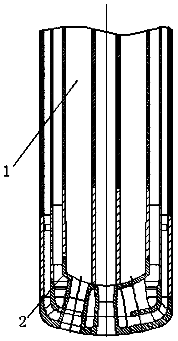
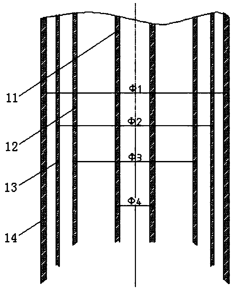
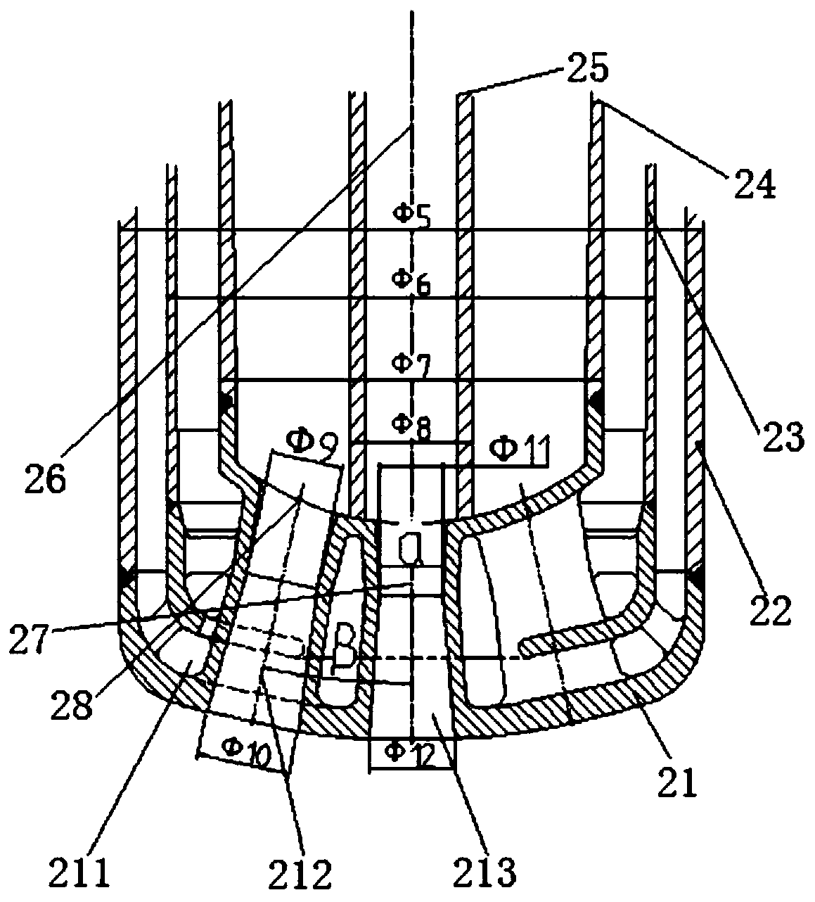
[0033] From Figure 1-3 It can be seen that a kind of molten iron dephosphorization device of the present embodiment includes a gun body assembly 1 and a nozzle assembly 2, and the gun body assembly 1 is composed of a gun body tube 11, a gun body intermediate tube 12, a gun body water inlet pipe 13 and a gun body assembly 1. The gun body return pipe 14 is composed of the gun body pipe 11, the gun body intermediate pipe 12, the gun body water inlet pipe 13 and the gun body return water pipe 14, which are coaxial cylinders, the gun body tube 11, the gun body intermediate pipe 12, the gun body The diameters of the water inlet pipe 13 and the gun body return pipe 14 are respectively denoted as Ф4, Ф3, Ф2 and Ф1, and the outer side of the inner tube 11 of the gun body is provided with a gun body intermediate pipe 12, and the outer side of the gun body intermediate pipe 12 is provided with a gun body water inlet pipe 13 , the outside of the gun body inlet pipe 13 is provided with a ...


PUM


Abstract

The invention discloses a molten iron dephosphorization device and method, and belongs to the technical field of steel smelting. The molten iron dephosphorization device comprises a gun body assemblyand a spray head assembly. The gun body assembly is composed of a gun body inner pipe, a gun body intermediate pipe, a gun body water inlet pipe and a gun body water return pipe. The spray head assembly is composed of a spray head body, a spray head water return pipe, a spray head water inlet pipe, a spray head intermediate pipe, and a spray head inner pipe. The upper end of the spray head inner pipe communicates with the gun body inner pipe. The upper end of the spray head intermediate pipe communicates with the gun body intermediate pipe. The upper end of the spray head water inlet pipe communicates with the gun body water inlet pipe. The upper end of the spray head water return pipe communicates with the gun body water return pipe. A cooling water channel, an outer spray hole and an inner spray hole are formed in an inner cavity of the spray head body. The molten iron dephosphorization device is provided with two independent air supply channels, namely an oxygen channel and a nitrogen channel, and corresponding Lavel spray holes, so that hybrid blowing of oxygen and nitrogen can be achieved under a low top oxygen supply strength condition, the dynamic condition of the upper portion of a molten bath of a converter is improved, and the purpose of high-efficiency, low-consumption and environment-friendly dephosphorization is achieved.

Description

technical field [0001] The invention relates to the technical field of iron and steel smelting, and more specifically relates to a device and method for dephosphorizing molten iron. Background technique [0002] Phosphorus is a harmful element in most steels. It is easy to segregate at grain boundaries, causing low temperature brittleness and temper brittleness. In order to meet the rising phosphorus content of raw materials and the market demand for ultra-low phosphorus steel, hot metal dephosphorization came into being. Dephosphorization of molten iron can be divided into two processes: oxidative dephosphorization and reductive dephosphorization. At present, oxidative dephosphorization is generally used in steel mills. The commonly used dephosphorization process is divided into two categories: one is dephosphorization in molten iron tanks or torpedo tanks, and the other is dephosphorization of molten iron in converters. These two methods mainly have the following problems:...

Claims


Application Information

Patent Timeline
Patent Type & Authority Applications(China)
IPC IPC(8): C21C7/064C21C1/02
CPCC21C7/064C21C1/02Y02P10/20
Inventor 徐小伟徐葆春王泉毛鸣
Owner MAANSHAN IRON & STEEL CO LTD
Features
  • R&D
  • Intellectual Property
  • Life Sciences
  • Materials
  • Tech Scout
  • Unparalleled Data Quality
  • Higher Quality Content
  • 60% Fewer Hallucinations
Learn More