
Pile body pneumatic reinforcement method

A pile and gas technology, applied in soil protection, protection devices, buildings, etc., can solve the problems of easy failure, insufficient storage capacity, poor corrosion resistance of pumps, etc., to prevent safety accidents and environmental pollution, acid resistance, etc. The effect of strong alkali salt and oxidizing ability, and strong operation reliability

Inactive Publication Date: 2019-09-10
付文堂
View PDF6 Cites 2 Cited by
  • Summary
  • Abstract
  • Description
  • Claims
  • Application Information

AI Technical Summary

Problems solved by technology

[0002] At present, most mine tailings ponds have problems such as low initial dam body strength, impervious tailings ponds, and insufficient stockpiling capacity; chemical waste slag yards and domestic waste landfills that are surrounded by anti-seepage membranes also have varying degrees However, there are problems of low strength of the pile body and leakage at the bottom, which can easily cause safety accidents such as pile body collapse and environmental pollution. The existing treatment method is to drill holes on the pile body and lower the submersible pump to pump water outward. The disadvantage of this method is that 1. The water pump has poor corrosion resistance, and the damage is not easy to repair
2. The drainage effect is not good or it is easy to fail after the pile body settles and deforms
3. The upper part of the pile cannot continue to pile up solid waste, causing the area of ​​the solid waste pile to become larger and larger, thereby causing environmental pollution

Method used


Image

  • Pile body pneumatic reinforcement method
  • Pile body pneumatic reinforcement method

Examples


Embodiment Construction

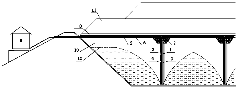
[0022] A method for aerodynamic reinforcement of a stack, comprising the following steps:

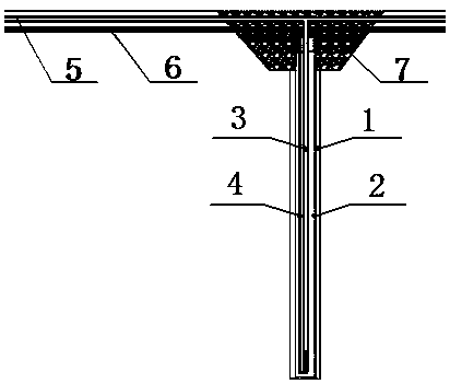
[0023] Step 1: Drill holes according to the specified number, angle and depth on the original pile body 10 containing interstitial water or gas to form a bottom-up drilling channel 1;

[0024] Step 2, put the seepage pipe 2 wrapped with a filter net into the passage in the above-mentioned drilled passage 1, so as to collect the infiltrated water;

[0025] Step 3, connect the outlet pipe 3 and the inlet pipe 4 with an elbow and bundle them together. Specifically, one end of the inlet pipe 4 can be changed in direction by 180 degrees with an elbow, and inserted into the outlet pipe 3, and the other end of the inlet pipe 4 is connected to the air intake system. 6;

[0026] Step 4, insert the outlet pipe 3 and the inlet pipe 4 into the seepage pipe 2, preferably at the bottom of the seepage pipe 2;

[0027] Step 5, connect the other ends of all outlet pipes 3 in series with plastic pipes,...


PUM


Abstract

The invention discloses a pile body pneumatic reinforcement method. The pile body pneumatic reinforcement method includes the steps that holes with the specified quantity, angle and depth are drilledon an original pile body to form a bottom-up channel; in the channel, a water seepage pipe wound with a filter screen is put into the channel to collect infiltration water; water outlet pipes and an air inlet pipe are connected and tied together with elbows; the water outlet pipes and the air inlet pipe are inserted into the water seepage pipe; all water outlet pipes are connected in series with pipes to be connected with a waste water collecting tank outside the pile body; concrete pouring is used for the joint of a channel mouth and the pipes; a newly arranged impermeable layer is laid on the original pile body; and an installation machine room is connected with an air inlet system and the air inlet pipe. The pipe body is solidified by extracting the water from the original pile body, the intensity of the pile body is strengthened, the pile body pneumatic reinforcement method has the characteristics of high operational reliability, re-stockpiling on the original pipe body, resistanceto settlement deformation of the pipe body and corrosion resistance.

Description

technical field [0001] The invention belongs to a reinforcement method for stockpiling of mine tailings in industrial solid waste, stockpiling of chemical waste slag and stockpiling of domestic garbage in domestic solid waste, and specifically refers to a method for pneumatically reinforcing piles. Background technique [0002] At present, most mine tailings ponds have problems such as low initial dam body strength, impervious tailings ponds, and insufficient stockpiling capacity; chemical waste slag yards and domestic waste landfills that are surrounded by anti-seepage membranes also have varying degrees However, there are problems of low strength of the pile body and leakage at the bottom, which can easily cause safety accidents such as pile body collapse and environmental pollution. The existing treatment method is to drill holes on the pile body and lower the submersible pump to pump water outward. The disadvantage of this method is that 1. The water pump has poor corros...

Claims


Application Information

Patent Timeline
Patent Type & Authority Applications(China)
IPC IPC(8): E02D31/00E02D3/10
CPCE02D3/10E02D31/006
Inventor 付文堂
Owner 付文堂
Learn More