
Novel flue gas thermal oil recovery equipment

A technology for thermal oil recovery and flue gas, which is applied in the fields of fluid extraction, earth-moving drilling, cleaning appliances, etc. It can solve the problems of high temperature gas pollutants, consumption of large fossil fuels, and large structure, and achieve the reduction of greenhouse effect, reasonable structure, The effect of saving flue gas generating device

Pending Publication Date: 2019-09-10
新疆科瑞石油工程技术服务有限公司
View PDF9 Cites 2 Cited by
  • Summary
  • Abstract
  • Description
  • Claims
  • Application Information

AI Technical Summary

Problems solved by technology

[0002] At present, oilfield flue gas drive technology has been widely used in oil production stimulation operations, but the conventional technology needs to provide a separate flue gas generating device (such as a boiler), purification device, cooling device, booster device (such as a diesel engine driven booster machine), etc., the power components of these devices not only need to consume a large amount of fossil fuels and produce high-temperature gas pollutants, but also have a relatively large structure and a relatively complicated process flow
At present, there is no literature report on the use of engine flue gas thermal injection well production

Method used


Image

  • Novel flue gas thermal oil recovery equipment

Examples


Embodiment Construction

[0020] The following is a further description of the present invention in conjunction with the accompanying drawings and embodiments.

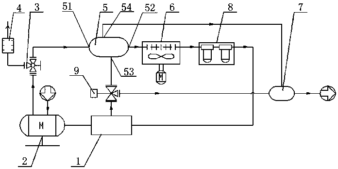
[0021] refer to figure 1 , a new type of flue gas thermal oil recovery equipment, including waste heat recovery heat exchange system, flue gas pressurization system, cooling system, purification and filtration system, gas mixing system and flow regulation control system.

[0022] The flue gas booster system is mainly composed of a flue gas booster 1, which can boost the flue gas pressure to a maximum of 50Mpa. The flue gas booster 1 should be selected to be resistant to flue gas acid gas corrosion;

[0023] The waste heat recovery heat exchange system is mainly composed of waste heat recovery heat exchanger 5. The waste heat recovery heat exchanger 5 is a tank structure with built-in heat exchange coils. The supercharged low-temperature flue gas provides a heat exchange unit, and the temperature of the supercharged flue gas after heat exchang...


PUM


Abstract

The invention discloses novel flue gas thermal oil recovery equipment. The novel flue gas thermal oil recovery equipment comprises a waste heat recovery heat-exchange system, a flue gas pressurizing system, a cooling system, a purification filtering system, a gas mixing system and a flow adjusting and control system; an inlet of the waste heat recovery heat-exchange system communicates with a fluegas outlet of an engine; the flue gas pressurizing system is connected with the engine and connected with the waste heat recovery heat-exchange system; an outlet of the waste heat recovery heat-exchange system is sequentially connected with the cooling system and the purification filtering system; and an inlet of the gas mixing system is connected with a second flow path outlet of the waste heatrecovery heat-exchange system and the outlet of the flue gas pressurizing system, an inlet of the flow adjusting and control system is connected with the flue gas pressurizing system, and an outlet ofthe flow adjusting and control system is connected with the waste heat recovery heat-exchange system and the gas mixing system. The novel flue gas thermal oil recovery equipment utilizes flue gas generated by the engine in a power system of the novel flue gas thermal oil recovery equipment to be recovered for incremental oil production operation, a flue gas generation device is omitted, and energy reutilizing and zero emission of exhaust gas are achieved.

Description

technical field [0001] The invention relates to the technical field of waste gas treatment and oil recovery, in particular to a novel flue gas thermal oil recovery equipment. Background technique [0002] At present, oilfield flue gas drive technology has been widely used in oil production stimulation operations, but the conventional technology needs to provide a separate flue gas generating device (such as a boiler), purification device, cooling device, booster device (such as a diesel engine driven booster machine), etc., the power components of these devices not only need to consume a large amount of fossil fuels and produce high-temperature gas pollutants, but also have a relatively large structure and a relatively complicated process flow. At present, there is no literature report on the use of engine flue gas thermal injection well production. Contents of the invention [0003] The object of the present invention is to address the defects of the prior art, and provi...

Claims


Application Information

Patent Timeline
Patent Type & Authority Applications(China)
IPC IPC(8): E21B43/24E21B37/00
CPCE21B43/24E21B37/00
Inventor 付万春牟学益申明乾孟巧玲安同武王玉军李东元董玉欣王延鹏王家步张新军李建奎游艳平罗庆瑞
Owner 新疆科瑞石油工程技术服务有限公司
Learn More