Hydraulic power-mechanical TBM cutter head combined rock breaking method, hydraulic power-mechanical combined rock breaking TBM cutter head and hydraulic power-mechanical combined rock breaking TBM device

A technology of mechanical and cutter head, applied in the fields of hydraulic-mechanical TBM cutter head combined rock breaking, hydraulic-mechanical combined rock breaking TBM device, hydraulic-mechanical combined rock breaking TBM cutter head, can solve the problem of low achievability, cutting The overall structure of the disc has changed greatly, so as to reduce the energy consumption of rock breaking, optimize the arrangement of the cutter head, and improve the rock breaking efficiency.

Pending Publication Date: 2019-09-10
INST OF ROCK AND SOIL MECHANICS - CHINESE ACAD OF SCI
View PDF2 Cites 10 Cited by
  • Summary
  • Abstract
  • Description
  • Claims
  • Application Information

AI Technical Summary

Problems solved by technology

[0008] Chinese patent number: CN105736006A, the patent name is "High Pressure Water Jet Full-Section Rock Tunneling Machine Cutter Design Method", the inventors Huo Junzhou, Zhu Dong, etc. disclosed a shape that changed the traditional circular cutter head, using two The cross-shaped spoke layout, through the impact of the water jet on the four spokes and the rotary extrusion of the cutter, is used to break the rock. The overall structural form has changed a lot, and the degree of industrial realization is not high

Method used


Image

  • Hydraulic power-mechanical TBM cutter head combined rock breaking method, hydraulic power-mechanical combined rock breaking TBM cutter head and hydraulic power-mechanical combined rock breaking TBM device
  • Hydraulic power-mechanical TBM cutter head combined rock breaking method, hydraulic power-mechanical combined rock breaking TBM cutter head and hydraulic power-mechanical combined rock breaking TBM device
  • Hydraulic power-mechanical TBM cutter head combined rock breaking method, hydraulic power-mechanical combined rock breaking TBM cutter head and hydraulic power-mechanical combined rock breaking TBM device

Examples


Embodiment Construction

[0081] The implementation of the present invention will be described in detail below in conjunction with the accompanying drawings, but they do not constitute a limitation to the present invention, and are only examples. At the same time, the advantages of the present invention are clearer and easier to understand through the description.

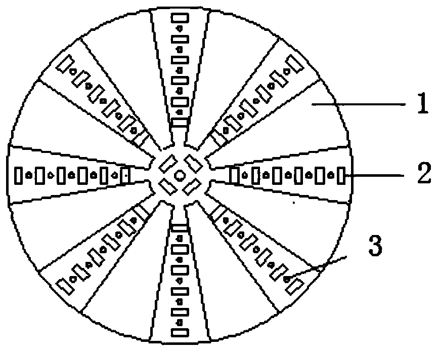
[0082] Referring to the accompanying drawings, it can be seen that the hydraulic-mechanical TBM cutter head combined rock breaking method includes the following steps,

[0083] Step 1: Install the combined rock-breaking TBM cutter head 4, and align the combined rock-breaking TBM cutter head 4 with the position of the cavern to be excavated (ie, the tunnel surface 18); the mechanical hob structure equipped on the TBM cutter head has enough Strong strength and rigidity, able to withstand the huge reaction force and shear stress generated by the cutterhead rotation and advancement during the excavation of the main engine;

[0084] Step 2: Fix...


PUM


Abstract

The invention discloses a hydraulic power-mechanical TBM cutter head combined rock breaking method. The hydraulic power-mechanical TBM cutter head combined rock breaking method comprises the steps that a combined rock breaking TBM cutter head is installed, and the combined rock breaking TBM cutter head is aligned to the position of a to-be-excavated grotto; a TBM outer machine frame is fixed, anda combined rock breaking TBM is started and is enabled to tunnel forwards for a stroke; and the referred steps are repeated, the next stroke operation is started until tunneling is carried out to a specified distance, and excavation of the grotto is completed. The hydraulic power-mechanical TBM cutter head combined rock breaking method has the advantages of suitable penetration degree and high rock breaking efficiency. The invention further discloses the hydraulic power-mechanical combined rock breaking TBM cutter head adopted by the hydraulic power-mechanical TBM cutter head combined rock breaking method. The invention further discloses a hydraulic power-mechanical combined rock breaking TBM device adopted by the hydraulic power-mechanical TBM cutter head combined rock breaking method.

Description

technical field [0001] The invention relates to the field of tunnels and underground engineering, in particular to the field of TBM tunnel construction under complex geological conditions, more specifically, it is a hydraulic-mechanical TBM cutter head combined rock breaking method. The present invention also relates to the hydraulic-mechanical combined rock-breaking TBM cutter head adopted in the hydraulic-mechanical TBM cutter head combined rock-breaking method. The present invention also relates to a hydraulic-mechanical combined rock-breaking TBM device adopted in the hydraulic-mechanical TBM cutter head combined rock-breaking method. Background technique [0002] The traditional TBM uses a mechanical hob to break rock, and the TBM hob often has three states when breaking rock, namely, small penetration, proper penetration and excessive penetration. [0003] Under the condition of a certain hob spacing, if the penetration is too small, the cracks generated under the cut...

Claims


Application Information

Patent Timeline
Patent Type & Authority Applications(China)
IPC IPC(8): E21D9/087E21D9/10E21D9/12
CPCE21D9/0621E21D9/087E21D9/1066E21D9/12
Inventor 卢景景徐福通周辉张传庆邱浩权
Owner INST OF ROCK AND SOIL MECHANICS - CHINESE ACAD OF SCI
Why Eureka
Try Eureka