Roller cone bit and construction method

A technology of roller cone bits and roller cones, which is applied to drill bits, earth-moving drilling, drilling equipment and other directions, can solve the problems of prone to broken teeth, low driving efficiency, single tooth landing, etc., to improve the speed of rock breaking and good impact. The effect of rock breaking and the effect of increasing the drilling pressure

Active Publication Date: 2021-10-19
源石机械科技承德有限公司
View PDF8 Cites 0 Cited by
  • Summary
  • Abstract
  • Description
  • Claims
  • Application Information

AI Technical Summary

Problems solved by technology

[0005] All of the above-mentioned prior art adopt full tooth structure, and mainly use the cutting teeth on the cone to squeeze and scrape the rock to break the rock. With the increasing requirements for the efficiency of excavation operations, the structure with full teeth is difficult to meet the needs of use. The defects of the structure with full teeth are mainly: irregular teeth, resulting in irregular teeth landing in the process of operation. The efficiency of rock breaking by rolling is low; in the process of operation, a single tooth often appears on the ground, and excessive pressure cannot be applied during the excavation process, resulting in low excavation efficiency and prone to broken teeth, and the service life of the cone is short; When two cones are operating at the same time, they cannot be on the same trajectory. Different operating trajectories affect the construction efficiency and the life of the cones.

Method used


Image

  • Roller cone bit and construction method
  • Roller cone bit and construction method
  • Roller cone bit and construction method

Examples


Embodiment 1

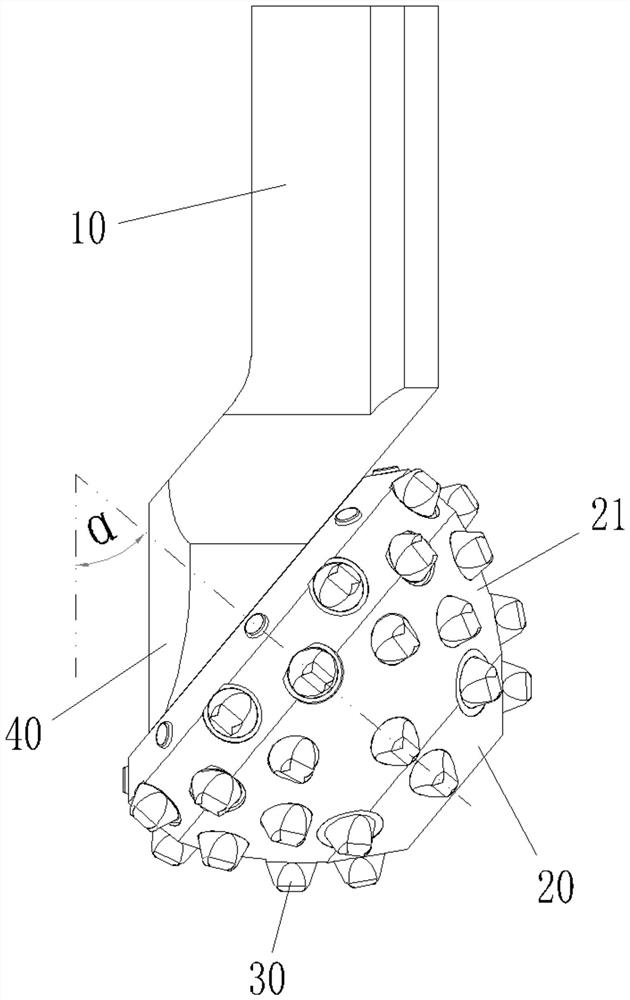
[0062] A single roller cone bit includes a bit body 10, a roller cone 20 and multiple rows of teeth 30.

[0063] The roller cone 20 is connected to the drill body 10 through an offset palm journal 40 and is arranged to be rotatable relative to the drill body 10, wherein the angle between the axis of the palm journal 40 and the feed axis of the drill body 10 is α is 40°-60°, for example figure 2 In the case where the included angle α is 50°, when the drill bit is working, the bit body 10 rotates to drive the cone 20 to rotate around its axis, and the cone 20 will also roll around its own axis.

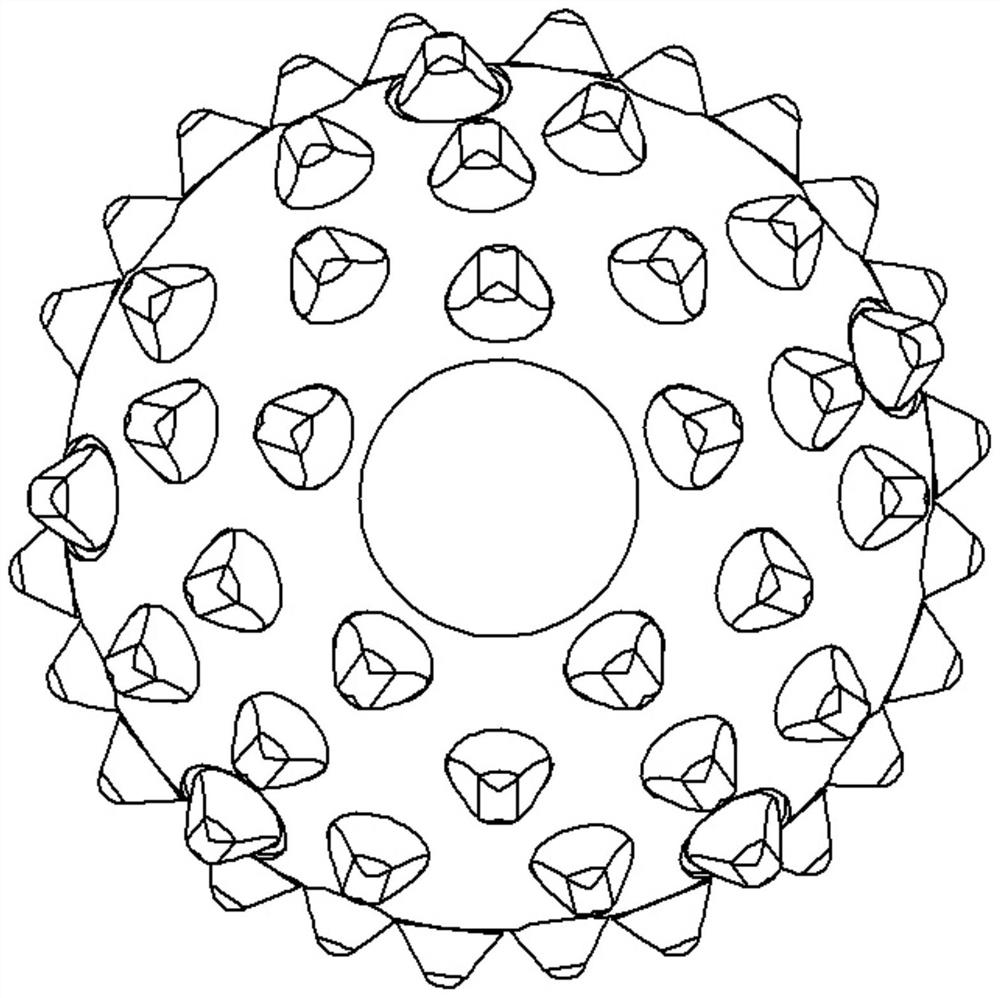
[0064] The cone 20 is in the shape of a truncated cone as a whole, and its generatrix is ​​an arc. A conical tooth surface 21 is formed on the outer peripheral wall of the cone 20. Multiple sets of teeth 30 are arranged on different meridians of the conical tooth surface 21. Each Each row of teeth 30 contains more than two teeth, so as to avoid the occurrence of a single tooth landing...

Embodiment 2

[0075] A combined roller cone bit, including two roller cone bits 50, a mounting base 60 and an impact device 70, wherein the structure of the roller cone bit 50 and the distribution of teeth are shown in detail in Embodiment 1, and will not be repeated here. Only to introduce the cooperative use structure of the roller cone bit 50 and the impact device 70, and in the single roller cone bit 50, the impact device 70 can still be used. For details, please refer to the following structure:

[0076] Such as Image 6 As shown, the impact device 70 includes a movable shaft 71 , an energy storage element 72 , a balancing pressure head 73 (balance element) and a support 74 .

[0077] Two roller cone bits 50 are oppositely installed on the mounting base 60, and the bit body 10 in the roller cone bit 50 is parallel to the axis of the movable shaft 71, and the movable shaft 71 is fixedly connected with the mounting base 60, and the movable shaft 71 can expand and contract along the feed...

Embodiment 3

[0086] A method for constructing teeth on a cone, for forming the cone bit of the structure in Example 1, which includes arranging the teeth on the cone in the following manner:

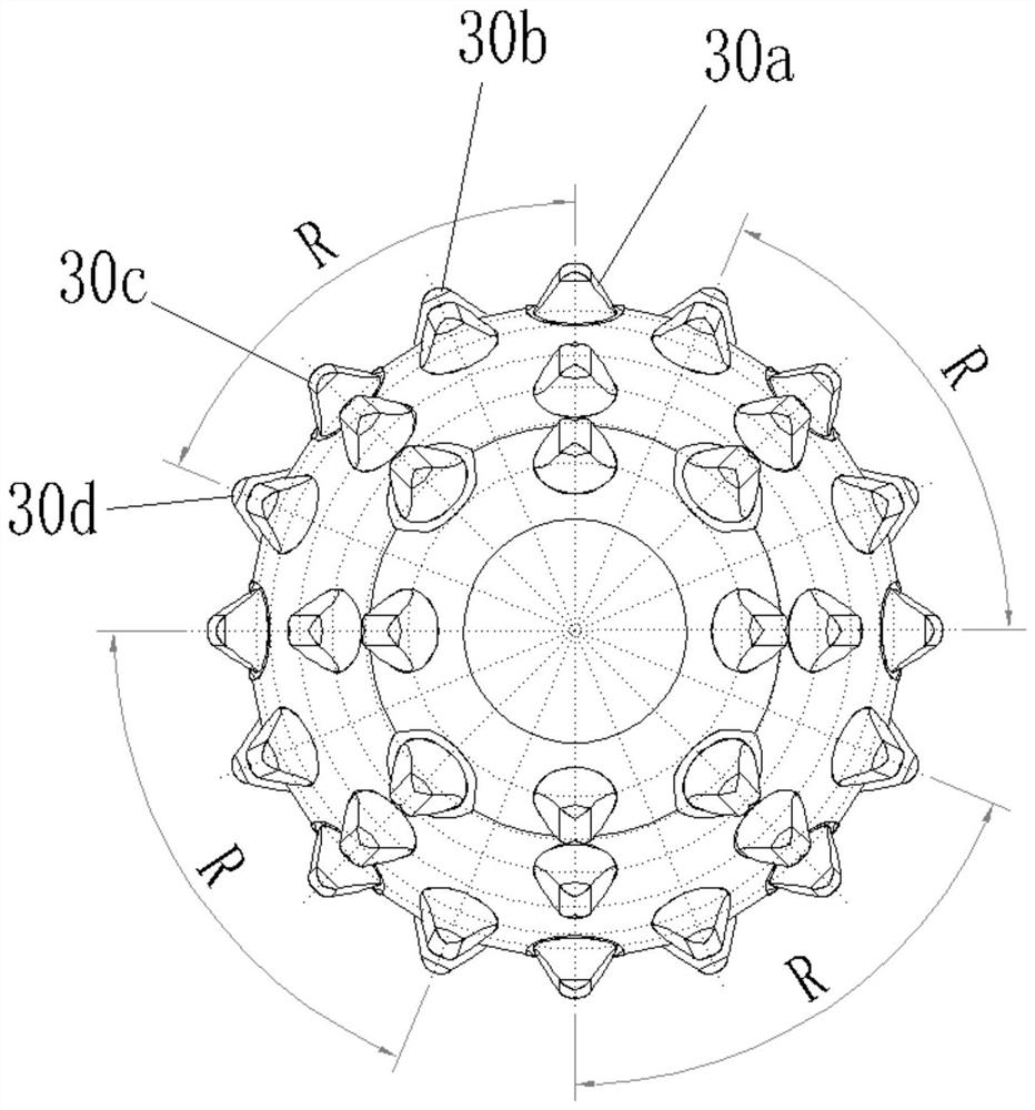
[0087] Multiple sets of rows of teeth 30 are arranged along the radial line of the cone 20, and the multiple sets of rows of teeth 30 that land sequentially produce a periodic drop, and during the sequential landing of adjacent rows of teeth 30, the center of the cone 20 can generate a gap along its radial direction. The impact displacement in the direction, and the impact displacement value generated by it is above 0.6mm.

[0088] Among them, a preferred size of the gear cone is: the diameter of the cone bottom (large end) is 128mm, the diameter of the cone top (small end) is 44mm, the overall height is 80mm, and the radius of the arc-shaped generatrix is ​​145mm. The included angle between the axis of 40 and the feed axis of the drill body 10 is α and is 50°. By setting sixteen groups of rows of te...


PUM


Abstract

The invention provides a roller cone bit and a construction method. The roller cone bit includes a bit body, a roller cone and a plurality of rows of teeth, wherein the roller cone is connected to the bit body through an offset palm journal, and is arranged to be able to relatively The bit body rotates, and there is a tapered tooth surface on the outer peripheral wall of the cone; multiple groups of teeth are arranged on different meridians of the tapered tooth surface, and each row of teeth contains more than two teeth; multiple groups of teeth During the grounding process of the teeth in sequence, the center of the cone produces a periodic displacement along its radial direction, so that the grounded row of teeth simultaneously generates cutting force along the direction of the tangential component and impact force along the direction of the radial component. In the rolling operation, the present invention realizes the sequence of multiple sets of gears and regular landing, and the center of the cone produces a relatively large relative displacement in its radial direction, which has the advantages of high rolling and rock breaking efficiency and long service life of the cone. advantage.

Description

technical field [0001] The invention relates to the technical field of engineering machinery, in particular to a roller cone bit and a construction method of the upper teeth of the roller cone. Background technique [0002] The drill bit is a rock-breaking tool used to break rocks and form a wellbore in drilling engineering; at present, the cones used in rock excavation are derived from the tooth arrangement transformation of petroleum tri-cone bits, that is, the "full teeth (no leakage rock cloth) Tooth)", its structure is as figure 1 As shown, the principle of tooth placement is "open spread", "uniform pressure point (operation point)", and "no large rock ridges left in the lip shape of the operation". [0003] For example, Chinese patent application 201010158245.9 discloses a roller cone bit, including: a drill body with a journal portion; a tapered portion capable of rotating relative to the drill body; a support portion located between the tapered portion and the journ...

Claims


Application Information

Patent Timeline
Patent Type & Authority Patents(China)
IPC IPC(8): E21B10/20E21B10/16
CPCE21B10/16E21B10/20
Inventor 吴方晓赵文武
Owner 源石机械科技承德有限公司
Why Eureka
Try Eureka